Parallel connection – HMC Electronics MDL Series BK Precision DC Electronic Load System Module User Manual
Page 32
32
There are two input connectors. One is the electronic load’s input measurement terminal and the
other is the Vsense measurement terminal. When Vsense is connected to device to be measured,
the electronic load will switch to Vsense mode automatically. There is no need to change a setting
in the menu and the front panel of the module will show “sense”.
CAUTION : The electric potential on the positive terminal of Vsense connector must
be higher than the negative terminal.
Parallel Connection
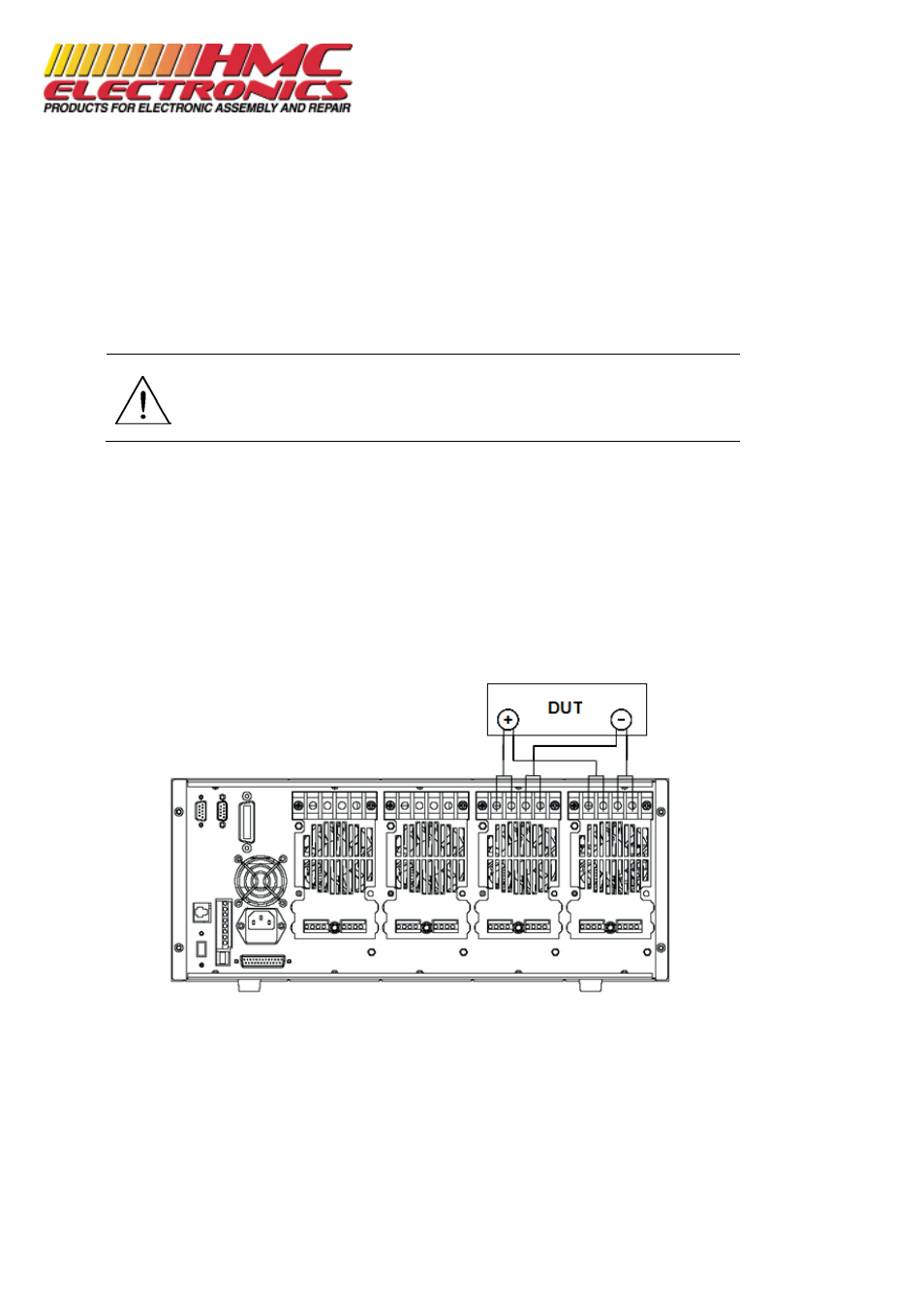
Parallel connection can be applied between modules of the same model to increase current and
power dissipation, but it cannot be applied between different modules. Modules can be paralleled
in CC, CR, or CW mode, but cannot be paralleled in CV or CZ mode. Each module will dissipate the
power it has been programmed at. For example, after being paralleled, two single-channel
modules rated at 80V/40A/300W can dissipate up to 80V/80A/600W. Figure 13 illustrates the
paralleled connection for increased power dissipation.
Figure 13 - Parallel Module Connection
Documentation Provided By HMC Electronics
33 Springdale Ave. Canton, MA 02021
(800) 482-4440