Graff WASH-BASIN MIXER (with Wall-Mount Spout) User Manual
Page 8
IOG 2328.00
Rev. 1 December 2007
8
GB E
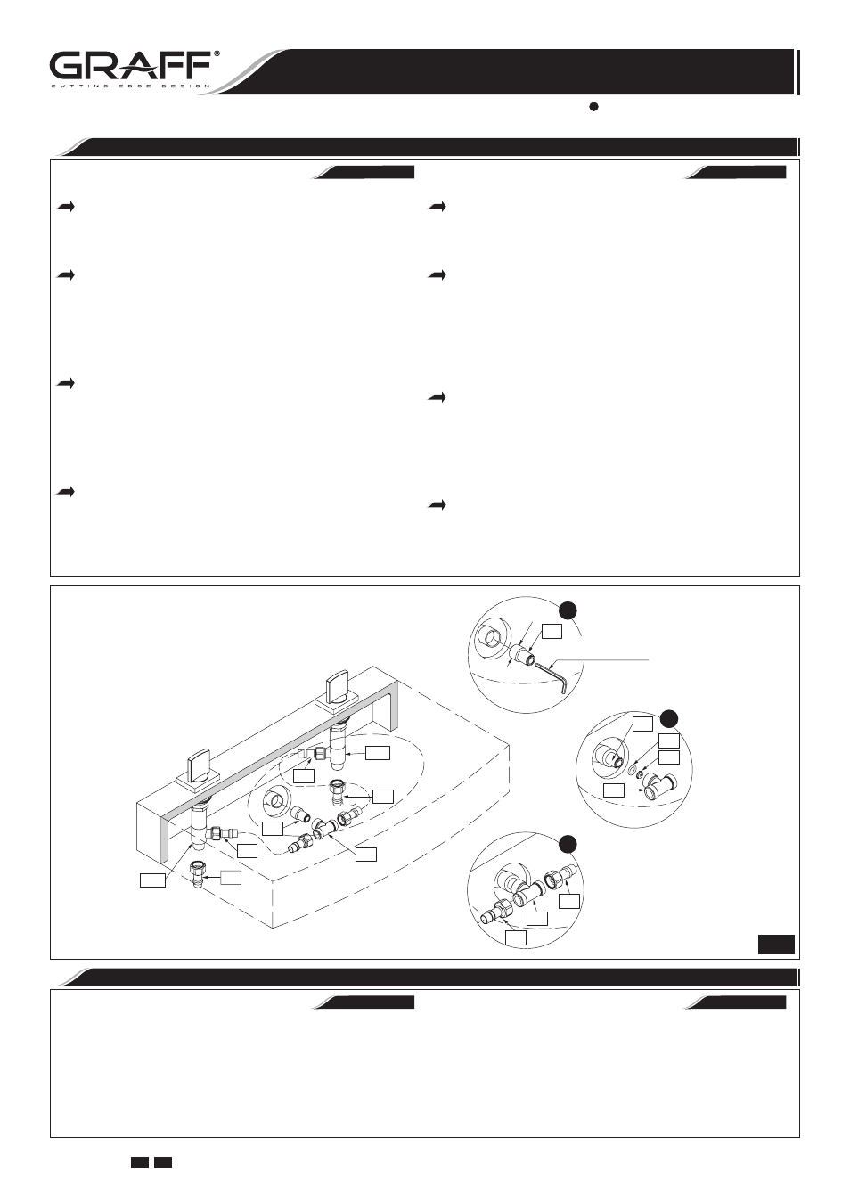
R1/2"
5/16" HEX KEY
LLAVE HEXAGONAL 5/16"
17
16
15
14
14
13
13
14
17
13
13
11B
11A
1
2
3
12
12
17
7
Levers are used to open and regulate the water flow. Full flow
is obtained by turning the lever through 90
0
(the cold water
tap on the right goes clockwise, the hot water tap on the left
counterclockwise). The intensity of the water flow is regulated
by positions between 0
0
-90
0
.
Para abrir la salida y la regulación del flujo del agua sirven las
palancas. La apertura total sucede al tornar la palanca por
el ángulo de 90
0
(de acuerdo con el movimiento de las mani-
llas del reloj en caso de la palanca del agua fría colocada en
el lado derecho, en contrario del movimiento de las manillas
del reloj en caso de la palanca del agua caliente colocada en
el lado izquierdo). La regulación de la intensidad del flujo de
agua sucede en las posiciones 0
0
-90
0
.
ESPAÑOL
ENGLISH
OPERATING INSTRUCTION
•
LA DESCRIPCIÓN DEL FUNCIONAMIENTO
ESPAÑOL
ENGLISH
MAKE CONNECTION TO WATER LINES
•
CONEXIÓN A LAS FUENTES DE AGUA
See fig. 1 & 7
The wash-basin mixer features flexible connecting
hoses (12) G1/2”-G3/8” with internal thread, 17-23/32”
(450mm) long. Pay attention that the hot and cold water
is correctly connected. It is recommended to mount ball
valves with a filter on the water supply.
Screw a nipple (17) into the ferrule of the system supply-
ing water to the spout connection rough (R). Use a 5/16”
hex key. The ferrule of the system supplying water to the
spout connection rough (R) should be equipped with a
water supply pipe with a G1/2” female thread placed in
the wall at such a height that it is possible to correctly
connect the valves (11A) and (11B) with the installed
T-connection (14) using the hoses (13).
Put the nozzle (15) and then the o-ring (16) into the
T-connection ferrule (14) as shown in fig. 7. You can grease
slightly the nozzle (15) and o-ring seal (16) with silicone,
so they would be kept in place in the socket of the T-con-
nection (14) during threading of the T-connection (14)
onto nipple (17). Screw the T-connection (14) onto the
nipple (17). Avoid using too much force while tightening
the connection.
Connect one end of the hoses (13) to the lateral outputs of
the valves (11A) and (11B) and the other to the installed
T-connection
(14).
Use adjustable wrench when tightening. Do not overtighten.
Ver dis. 1 y 7
El grifo del lavabo está equipada en manguitos de co-
nexión (12) G1/2”-G3/8” con rosca interior de longitud de
17-23/32” (450mm). Tenga en cuenta la conexión correcta
del agua fría y caliente. Es recomendable montar válvulas
de bola con filtro en la alimentación.
Al tubo corto de la instalación que suministra el agua al
conjunto de conexión cruda del caño (R) atornille el racor
(17). Para ello use la llave hexagonal 5/16”. El tubo corto
de la instalación que alimenta el conjunto de conexión cru-
da del caño (R) debería poseer una tubuladura con la rosca
interior de G1/2” situada en la pared a la altura que facilite
la conexión correcta a través de las mangueras (13) con
las válvulas (11A) y (11B) con el tubo en T (14) insta-
lado.
En el tubo corto central del tubo en T (14) meta la tobera
(15) así como está presentado en el dib. 7, luego meta la
junta o-ring (16). Puede poner un poco de silicona sobre
el inyector (15) y la junta o-ring (16) para impedir el
traslado de estos elementos en el asiento del tubo en T en
el momento de enroscar el tubo en T (14) sobre la pieza
de empalme (17). Atornille el tubo en T (14) en el racor
(17). No lo haga forzando al apretar.
Una las mangueras (13) por un lado a las salidas laterales
de las válvulas (11A) y (11B), y por el otro al tubo en T
instalado (14).
Utilice llaves ajustables cunado necesite ajustar alguna pieza.
No ajuste demasiado.
WASH-BASIN MIXER (with Wall-Mount Spout)
EL GRIFO DEL LAVABO (con Caño Montado en la Pared)
Installation Instructions Instrucciones de instalación