Flint & Walling SPJ User Manual
Page 5
5
© Copyright 2012. All rights reserved.
IL0183
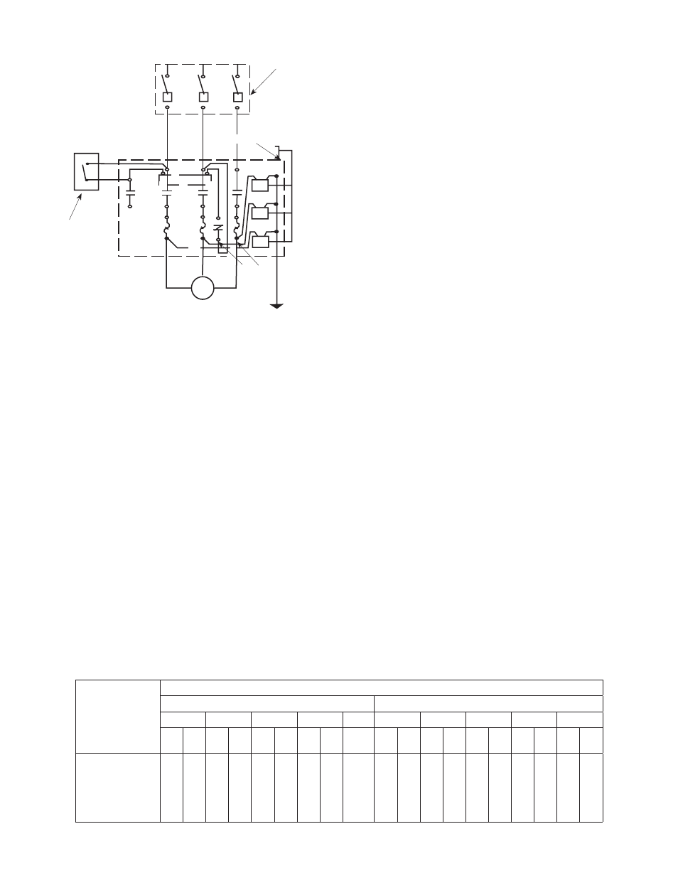
Figure 10 — Magnetic Starter Wiring Diagram — Three Phase
#10 or Heavier
Copper Ground
Wire. Connect to 8
ft. Ground Rod or
Well Casing
Lightening
Arrestors
Fused
Disconnect
Switch
Pressure
Switch
Motor
L3
L2
L1
W
T2
T1
1
X2 T3
V
M
3
2
T2
T1
T3
OPERATION
1. When installation has been completed, remove
the priming plug from the discharge tee (see
Figures 3-6) and fill the pump body and suction
pipe completely with water. No additional water
will be needed for subsequent start-ups unless
the pump body is drained.
2. After the pump is turned on it will require 2-5
minutes before all air is evacuated from the
suction line and water begins to flow. If there is
no water after 10 minutes turn the pump off and
check the following.
a. Any air leaks on the suction line must be
eliminated.
b. Suction pipe inlet should be a minimum of 5
feet below the water level.
c. Total suction lift cannot be greater than 25
feet.
d. Any restrictions in the discharge line, such as
a closed valve must be eliminated.
NOTE: Unit must be full of liquid before operating.
Never run dry, or against a closed discharge. Dry
running or running unit against a closed discharge
will cause damage to the shaft seal. Do not pump
dirty water or abrasive liquids, otherwise the same
may occur as if running dry.
MOTOR ROTATION
1. Single phase models are one rotation only
(counterclockwise when facing the pump suction
tapping) and cannot be reversed.
2. Proper rotation of pump impeller is critical for
three-phase pumps. Pump motor should turn
counterclockwise (CCW) when facing pump
suction tapping. Momentarily “bump” (apply
power for less than a second) the motor to check
for proper rotation. To change rotation on three-
phase units, interchange any two incoming line
(power) leads.
MAINTENANCE
Lubrication
1. The pumps and motors require no lubrication.
The ball bearings of the motor have been
greased at the factory. Under normal operating
conditions they should require no further
greasing.
Freezing
1. Drain the entire system if there is danger of
freezing. A drain plug is provided at the bottom
of the pump case for this purpose.
ROTARY SEAL ASSEMBLY REPLACEMENT
CAUTION: Make certain that the power supply is
disconnected before attempting to service the unit!
The rotary seal assembly must be handled carefully
to avoid damaging the precision lapped faces of the
sealing components.
See Parts List For Reference Numbers
1. Disengage pump body (Ref. No. 10) from motor
and mounting ring (Ref. No. 2) by removing bolts
(Ref. No. 11).
2. Remove diffuser bolts (Ref. No. 8) and remove
diffuser (Ref. No. 7).
3. Unthread impeller (Ref. No. 6). from motor shaft.
NOTE: To remove the impeller use a 9/16” open end
wrench to hold the motor shaft. The shaft flat area is
WIRE SIZE CHART (Figure 11)
Distance From
Motor To Fuse
Box, Meter or
Electrical Outlet
Minimum Copper Wire Size Chart (Gauge)
Single Phase Motors
Three Phase Motors
3/4 HP
1 HP
1-1/2 HP
2 HP
3 HP
3/4 HP
1 HP
1-1/2 HP
2 HP
3 HP
115
Volt
230
Volt
115
Volt
230
Volt
115
Volt
230
Volt
115
Volt
230
Volt
230
Volt
230
Volt
460
Volt
230
Volt
460
Volt
230
Volt
460
Volt
230
Volt
460
Volt
230
Volt
460
Volt
0-50 Ft.
50-100 Ft.
100-150 Ft.
150-200 Ft.
200-300 Ft.
Fuse Size (Amps)
12
12
10
10
8
20
14
14
14
12
12
15
10
10
10
8
6
30
14
14
12
12
10
15
10
8
6
*
*
30
12
12
12
10
10
20
10
8
6
*
*
30
12
12
12
10
10
20
10
10
10
10
8
30
14
14
14
14
14
15
14
14
14
14
14
15
14
14
14
14
12
15
14
14
14
14
14
15
14
14
14
12
12
15
14
14
14
14
14
15
14
14
14
12
10
15
14
14
14
14
12
15
14
14
14
12
10
15
14
14
14
14
12
15
(*) Not economical to run in 115V, use 230V