Flint & Walling SPJ User Manual
Page 3
3
© Copyright 2012. All rights reserved.
ELECTRICAL CONNECTIONS
GROUNDING
CAUTION: To reduce the risk of electric shock the
motor must be securely and adequately grounded
to a grounded metal raceway system, or by using a
separate grounding wire connected to bare metal on
the motor frame, or to the grounding screw located
inside motor terminal box, or other suitable means.
Refer to National Electric Code (NEC Article 250
{Grounding}) for additional information.
CAUTION: All wiring should be performed by a
qualified electrician and in accordance with the
national electric code and local electric codes.
WARNING: Failure to connect the motor frame to
equipment grounding conductor by using green
screw may result in serious electrical shock.
WIRING CONNECTIONS
1. This unit is not water proof and is not intended to
be used in showers, saunas, or other potentially
wet locations. The motor is designed to be
used in a clean dry location with access to
an adequate supply of cooling air. Ambient
temperature around the motor should not exceed
104F (40C). For outdoor installations motor
must be protected by a cover that does not block
airflow to and around the motor. This unit is not
weatherproof nor is it able to be submersed in
water, or any other liquid.
2. Single phase motors, 3/4 - 2 HP, are dual
voltage and can be connected for 115V or 230V
service. The 3 HP single phase motor is 230V
only. Single phase motors are factory connected
for 230V at the motor.
3. All three phase motors are 208-230/460 volts
and are factory connected at the motor for 230
volts.
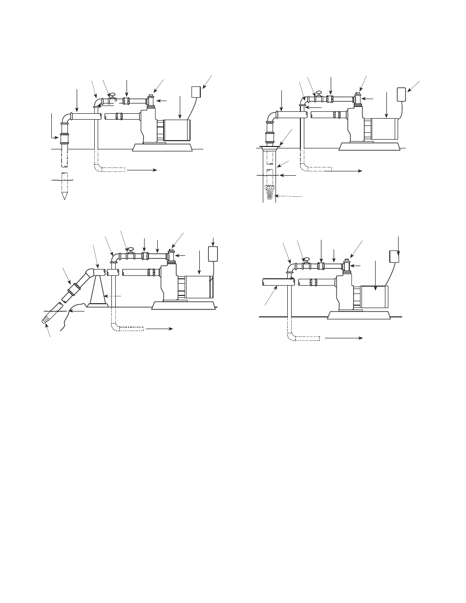
TYPICAL INSTALLATIONS
Figure 3 — From Ground Water “Drive Point”
Figure 6 — From City Water Main
Figure 5 — From Surface Water “Lake, Stream, Cistern or
Canal”
Figure 4 — From Ground Water “Well”
1 — Suction Pipe
2 — Discharge Pipe
3 — Elbow
4 — Gate Valve
5 — Union
6 — Discharge Tee
7 — Priming Plug
8 — Pump
9 — Fuse Box
1
2
3
4
5
7
8
9
1
2
3
4
5
6
7
8
9
1
2
3
4
5
6
7
8
1
3
4
5
7
8
9
Check
Valve
To Sprinkler System
Water Level
Drive Point
Well Seal
To Sprinkler System
Foot Valve With Screen
Well
Water Level
Pipe Support
Check Valve
Water
Level
Strainer
To Sprinkler System
To Sprinkler System
9
6
2
6