Flint & Walling SPJ User Manual
Page 2
2
© Copyright 2012. All rights reserved.
PIPING
1. Plastic or galvanized steel pipe may be used
in the installation. Plastic pipe must have a
minimum pressure rating 160 P.S.I. Galvanized
steel pipe must be in good condition free of rust
and scale. Threads should be sharp, cleanly
cut.
2. Both the suction and discharge pipe should be
no smaller than the corresponding tappings
of the pump (See Figure 1). If long runs are
encountered larger pipe should be used.
Smaller pipe will reduce the capacity of the
pump.
3. All joints and connections should have pipe
sealing compound (male threads only) applied
and drawn up tightly.
CAUTION: The entire system must be air and water
tight for efficient operation.
PUMP INSTALLATION
1. Refer to Figures 3, 4, 5, and 6 for typical
installations. If galvanized pipe is used, both the
suction and discharge pipe should be supported
at a point near the pump to avoid strains being
placed on the pump.
2. The suction pipe should slope upwards from the
water source to the pump. Locate the pump
as close to the water as possible keeping the
suction pipe as short as conditions permit.
3 Avoid dips or pockets in offset piping or air
will accumulate at high points which will make
priming difficult.
4. A foot valve located in the water or a check
valve located as close to the water as possible
will reduce priming time of the pump and help
maintain prime. A strainer must be used on the
suction line to filter out dirt and debris.
5. Install a gate valve and union in the discharge
line. For removal of the pump for service, close
the gate valve and disconnect the union.
CAUTION: Do not use a globe valve or other
restricting type of valve at the discharge. This will
seriously restrict the capacity of the pump.
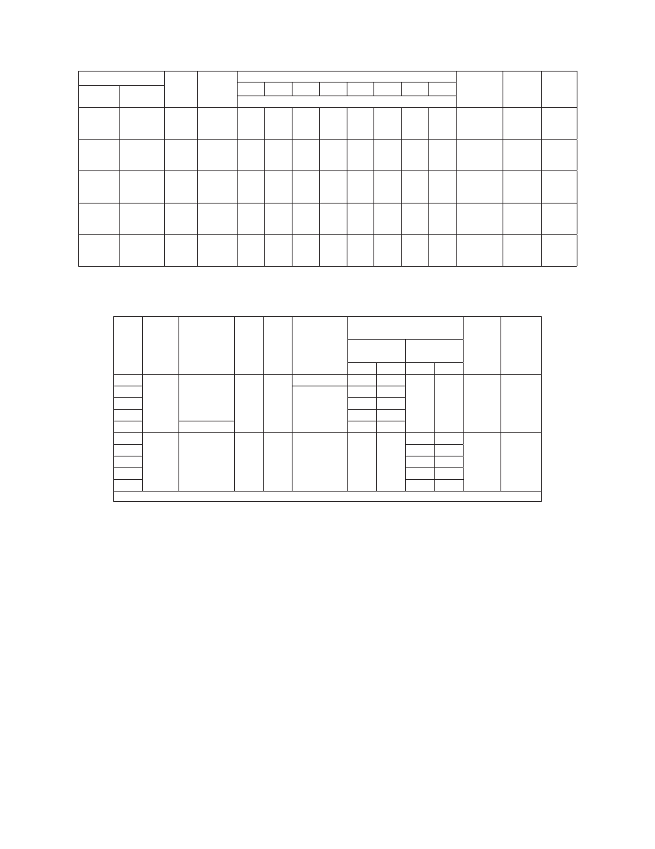
PERFORMANCE
Model Number
HP
Suction
Lift Ft.
Discharge Pressure PSI
Shut-Off
Pressure
PSI
Suction
Pipe Tap
Disch.
Pipe
Tap
10
15
20
25
30
35
40
45
1 Phase
3 Phase
Capacity - U.S. Gallons per Minute
SPJ07P1 SPJ07P3
3/4
5
15
25
56
47
43
48
42
37
42
37
31
37
29
22
29
22
10
21
12
41
37
33
2”
1-1/2”
SPJ10P1 SPJ10P3
1
5
15
25
58
53
48
53
48
44
48
45
38
43
37
33
38
31
25
32
24
14
23
12
11
48
43
39
2”
1-1/2”
SPJ15P1
SPJ15B1
SPJ15B3
1-1/2
5
15
25
78
70
47
77
68
46
74
66
45
70
62
44
62
53
42
53
43
34
43
30
30
47
41
36
2”
1-1/2”
SPJ20B1 SPJ20B3
2
5
15
25
86
76
52
84
74
51
81
72
50
77
69
47
71
64
45
62
55
42
52
43
30
40
25
50
45
40
2”
1-1/2”
SPJ30B1 SPJ30B3
3
5
15
25
88
77
54
86
76
53
85
75
52
84
74
51
80
72
50
73
65
49
64
55
45
53
43
10
54
50
45
2”
1-1/2”
Motor voltage: Single Phase: 3/4 - 2 HP - 115/230V 60Hz; Three Phase: 3/4 - 3 HP - 208-230/460V 50/60Hz
Maximum Case Pressure: 100 PSI
SPECIFICATIONS (Figure 2)
HP
Type
Volts/
Amps
Hz RPM
Motor
Voltage
(Factory)
Connected
Service Factor Motor
Amps
Max
Liquid
Temp
Max
Suction
Lift
Single
Phase
Three
Phase
115V 230V 230V 460V
3/4
Single
Ph
115/230
60
3450
115V
14.0
7.0
-
-
180˚F
25 Ft.
1
230V
18.0
9.0
1-1/2
21.0 10.5
2
25.0 12.5
3
230
-
13.5
34
Three
Ph
20/-230/460 60/50 3450/
2850
230V
-
-
3.5
1.75
180˚F
25 Ft.
1
4.5
2.25
1-1/2
5.7
2.85
2
7.4
3.70
3
9.8
4.90
Suction lift varies, depending upon elevation (altitude) and water temperatures.