Flint & Walling SPJ User Manual
Page 4
4
© Copyright 2012. All rights reserved.
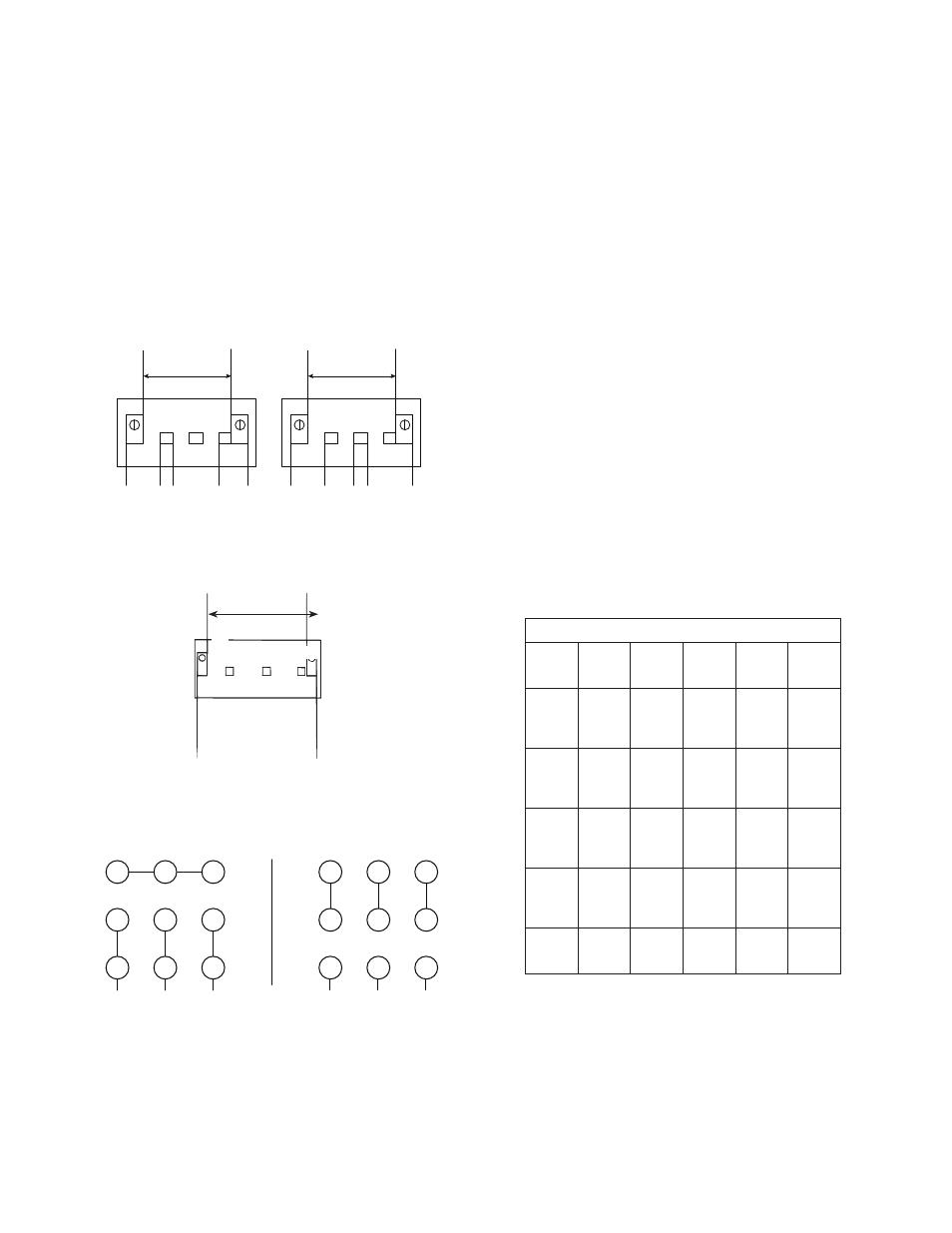
4. If the motor wiring must be changed to conform
to your specific voltage requirements then the
motor should be rewired. For proper electrical
connections, refer to the connection diagram
located on the nameplate of the motor or one of
the following diagrams. Make sure connections
are correct for the voltage being supplied to the
motor.
WARNING: Always disconnect power source before
performing any work on or near the motor or its
power source. Failure to do so could result in
personal injury or fatal electrical shock.
L1
L2
A
B
L1
L2
A
B
IL0180
YELLOW
115 VOLT
SINGLE PHASE
LINE
230 VOLT
SINGLE PHASE
LINE
WHITE
GRAY
RED
TAN
YELLOW
WHITE
GRAY
RED
TAN
Figure 7 — Wiring Diagram for Single Phase 3/4 - 2HP
CHECK VOLTAGE OF POWER
SOURCE BEFORE CONNECTING
DO NOT CONNECT ANY GROUND WIRE TO THESE LEADS
IL0181
Figure 7A — Wiring Diagram for Three Phase 3HP
DO NOT CONNECT ANY GROUND WIRE TO THESE LEADS
Line
230 Volts
Single Phase
B
A
L1
L2
Y
E
L
L
O
W
G
R
A
Y
4
5
6
7
8
9
1
2
3
4
5
6
7
8
9
1
2
3
L1
L3
L2
L1
L3
L2
3-
ø
IL0770
LOW VOLTAGE 230V
HIGH VOLTAGE 460 V
Figure 8 — Wiring Diagram for Three Phase
Connections for 3 Phase, 9 Leads
NOTE: To reverse rotation, interchange any two incoming line (power)
leads
MOTOR PROTECTION
1. All single-phase motors have built-in thermal
protection for all voltages. The overload protects
the motor against burnout from overload of
low voltage, high voltage and other causes.
The device is automatic and resets itself once
the temperature has dropped to a safe point.
Frequent tripping of the device indicates trouble
in the motor or power lines and immediate
attention is needed. The device should never be
tampered with unless the trouble is located and
corrected.
WARNING: Never examine, make wiring changes
or touch the motor before disconnecting the main
electrical supply switch. The thermal device may
have opened the electrical circuit.
2. Three-phase motors do not have built-in
thermal protection. It is recommended that a
properly sized magnetic or manual starter (both
with properly sized heaters) be used with all
three-phase motors. Install starters following
instructions of the starter manufacturer. See
Figure 10 for magnetic starter wiring program.
3. All motors (single and three phase) should be
equipped with a correctly fused disconnect
switch to provide protection. Consult local or
national electric codes for proper fuse protection
based on motor data chart. See Figures 9 & 11.
MOTOR DATA (Figure 9)
HP
Phase
Volts
Code
Letter
Max
Amps
Locked
Rotor
Amps
3/4
1
1
3
3
115
230
230
460
K
14.00
7.00
3.50
1.75
52.0
26.0
19.0
9.5
1
1
1
3
3
115
230
230
460
L
L
K
K
18.00
9.00
4.50
2.25
70.0
39.0
26.9
13.5
1-1/2
1
1
3
3
115
230
230
460
J
J
K
K
21.00
10.50
5.70
2.85
98.0
49.0
33.5
16.8
2
1
1
3
3
115
230
230
460
H
H
K
K
25.00
12.50
7.40
3.70
116.0
58.0
44.0
22.0
3
1
3
3
230
230
460
H
D
D
13.50
9.80
4.90
53.0
48.0
24.0
4. Undersize wiring can cause motor failure (low
voltage), frequent cut-out of motor overload
protector, television interference and even fire.
Make certain the wiring is adequately sized
(Figure 11), well insulated and connected to a
separate circuit outside the house in case of fire.