10 fault clearance, 11 technical data – Festo DRRD-08/10 User Manual
Page 4
10
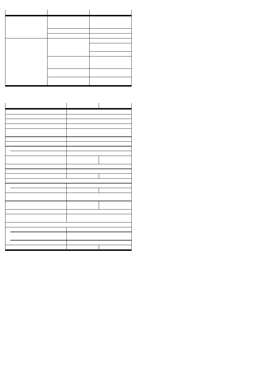
Fault clearance
Malfunction
Possible cause
Remedy
Uneven movement of the
payload
Flow control valves inserted
incorrectly
Check the flow control
function (supply or exhaust air
flow control)
Asymmetric angle setting
Symmetric setting preferred
DRRD defective
Return to Festo
Hard metal impact at the end
position
Flanged shaft does not remain
in the end position
(rebounding)
Residual energy too high
Select a lower swivel speed
Move only against residual air
cushion on the exhaust side
Select a lighter load
Semi-rotary drive moves
against an unpressurized
chamber
Pressurize semi-rotary drive
on both sides
Shock absorber unscrewed
too far
Observe the maximum
permissible unscrewing length
Cushioning component
defective/worn
Replace cushioning component
(
8 Disassembly and repair)
Fig. 18
11
Technical data
Size
8
10
Design
Semi-rotary drive with twin pistons
Cushioning
Elastic cushioning rings/plates at both ends
Pneumatic port
M3
Operating medium
Compressed air to ISO 8573-1:2010 [7:4:4]
Note on the operating medium
Lubricated operation possible (in which case
lubricated operation will always be required)
Operating pressure
[bar]
3 … 8
Mounting position
any
Swivel angle
[°]
180
Setting range on both sides
[°]
infinitely adjustable between –100 … +10
Cushioning angle (
Z minimum swivel
angle)
[°]
38
37
Repetition accuracy
[°]
≤ 0.03
Ambient temperature
[°C]
–10 … +60
Theoretical torque at 6 bar
[Nm]
0.2
0.4
Max. axial load (static)
Tension
[kN]
0.26
Pressure
[kN]
0.7
1.1
Max. permissible axial and radial
force on flanged shaft
dependent on the distance of the force
application point (
www.festo.com/catalogue)
Max. permissible mass moment of
inertia
[kgcm
2
] 15
20
End-position adjustment
by turning the cushioning components
Note on materials
Contains paint-wetting impairment substances
(PWIS)
Materials
Housing
Anodised aluminum
Flanged shaft, plug, shock absorber
retaining plate, screws
Steel
Seals
TPE-U (PU), NBR
Product weight
[kg]
0.16
0.25
Fig. 19