2 pneumatic installation, 3 electrical installation, 5 commissioning – Festo DRRD-08/10 User Manual
Page 2: 1 commissioning end-position adjustment
3. Pull tubing and cables through the
hollow flanged shaft, if necessary.
Diameter for wiring (
Fig. 6).
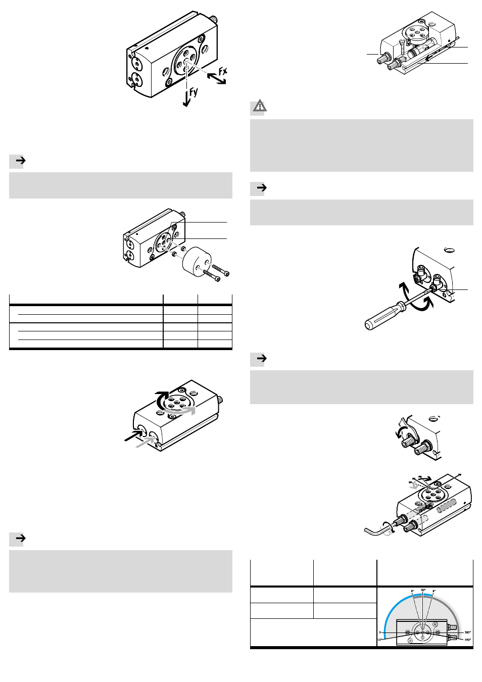
4. When mounting the payload, ob-
serve the following specifications:
– installation without tilting
– permissible radial force Fy
– permissible axial force Fx
– permissible mass moment of
inertia
– a structure that is as rotationally
symmetrical as possible.
Fig. 4
The mass moment of inertia of the payload should be calculated. Lever arms,
cantilevers and masses should be considered in the calculation (maximum per-
missible values
www.festo.com/catalogue).
Note
If there are demanding requirements for concentricity of the components on the
flanged shaft:
• Use the middle centring hole
4 as well as one of the 4 existing centring holes.
5. Secure the payload to the drive
flange at the mounting interface
5
by using at least two screws posi-
tioned opposite one another and
centring sleeves.
Observe the tightening torque
(
Fig. 6).
Fig. 5
5
4
Size
8
10
Shaft opening
4
[mm]
∅ 3
∅ 3
Centring sleeve ZBH for middle centring hole
[mm]
5
5
Screw for thread at
5
M3
M3
Centring sleeve ZBH
[mm]
5
5
Tightening torque
[Nm]
1.2
1.2
Fig. 6
4.2 Pneumatic installation
• If necessary, remove the covers in the
pneumatic ports.
To adjust the swivel speed:
• Use the GRLA one-way flow control
valves.
These are screwed directly into the
compressed air supply ports.
Fig. 7
For vertical installation and eccentric loads:
• Use the controlled check valve HGL or a compressed air spacer compensation
reservoir VZS.
In this way you can prevent the effective load from sliding down suddenly if
there is a sudden pressure drop.
4.3 Electrical installation
Note
Multiple switching cycles of proximity sensors are possible, dependent on the
design.
• Make sure the proximity sensors are always set to the first switching point.
To do this, push the cylinder switch (A
Fig. 8) in from the slot end where the
piston to be sensed is located until the first switching occurs.
• Place the proximity sensors for
sensing the end positions into the
slots
7.
Fig. 8
7
(A)
7
5
Commissioning
Caution
Danger of injury from rotating loads.
• Make sure the DRRD is only set into motion with protective devices.
• Make sure that in the swivel angle of the DRRD
– nobody can reach in
– no foreign objects can enter
(e.g. by means of an individual protective guard).
Note
• Comply with the following prerequisites:
– the shock absorbers are secured with lock nuts
– the operating conditions are within the permissible ranges.
5.1 Commissioning end-position adjustment
1. Rotate both upstream one-way flow
control valves (B):
– at first completely closed
– then open them again
approximately one turn.
2. Pressurize the drive optionally in one
of the following ways:
– slow pressurisation of one side
– simultaneous pressurisation of
both sides with subsequent
exhausting of one side.
(B)
Fig. 9
Note
Risk of damage!
If the shock absorber is unscrewed too far, it will result in the piston colliding
with the end cap with insufficient cushioning.
• Observe the permissible shock absorber settings (
Fig. 13).
3. Pressurize the corresponding port to
swivel the DRRD into the desired end
position.
4. Loosen the lock nut on the shock
absorber.
Fig. 10
5. Turn the corresponding shock
absorber until the desired end
position adjustment has been
reached.
Fig. 11
Angle setting
Reaction
Setting range related to the
basic factory setting (example
DRRD-...-180)
Turn the shock absorber
clockwise
Reduce the swivel angle
Turn the shock absorber
anti-clockwise
Increase the swivel angle
Fig. 12