1 write process, Write process, Manual eks electronic-key adapter usb – EUCHNER EKS FSA with USB Interface User Manual
Page 40
Manual EKS Electronic-Key Adapter USB
Page 40/44
Subject to technical modifications
094485-04-11/13
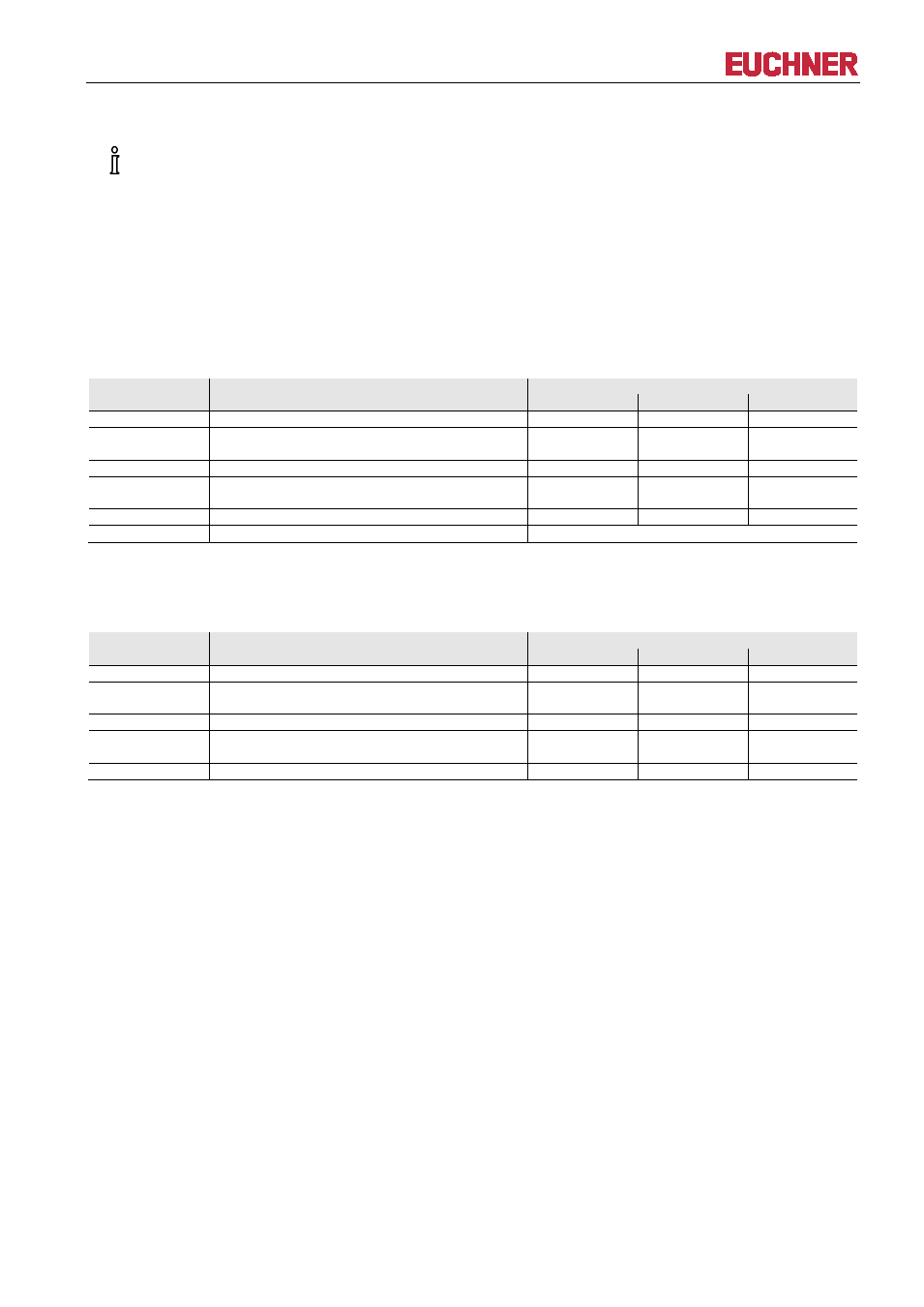
8.4.1 Write process
When this command is used, the Electronic-Key must be in the Electronic-Key adapter, and must be
removed from within the operating distance only after the reply message has been received.
Command message (message core, PC
→ EKS, see Figure 2):
TP (device addr.) (start addr. user data) (number of bytes of user data) (user data)
Reply message (message core, EKS
→ PC, see Figure 3):
RF (device addr.) (00
hex
, 00
hex
) (status number)
Byte no.
Description
Contents
ASCII
hexadecimal
decimal
0
Number of message bytes
0B ... 7B
11 ... 123
1
2
Command identification
T
P
54
50
84
80
3
Device address
01
1
4
5
Start address for the user data
00
00 ... 70
0
0 ... 112
6
Number of bytes of user data
04 ... 74
4 ... 116
7 ... 122
User data
ASCII or hexadecimal or BCD (code transparent)
Figure 2: Command message write to read/write Electronic-Key (message core)
Byte no.
Description
Contents
ASCII
hexadecimal
decimal
0
Number of message bytes
07
7
1
2
Command identification
R
F
52
46
82
70
3
Device address
01
1
4
5
Padding data
00
00
0
0
6
Status number
*
Figure 3: Reply message write to read/write Electronic-Key - status (message core)
* Status number
00
hex
: No error
02
hex
: Electronic-Key not in the operating distance
(For further status numbers see section 8.6)