Operating instructions position switch ng – EUCHNER NGxxx User Manual
Page 4
Operating Instructions Position Switch NG...
EUCHNER GmbH + Co. KG
Kohlhammerstraße 16
D-70771 Leinfelden-Echterdingen
Tel. +49/711/75 97-0
Fax +49/711/75 33 16
www.euchner.de
SR6WF
55
13,5
50
75
SR6EF
∅ 28
60
80
26
∅ 7 - 9
Subject to technical modifications; no r
esponsibility is accepted for the accuracy of this information.
© EUCHNER GmbH + Co. KG
0
32310-08-08/07
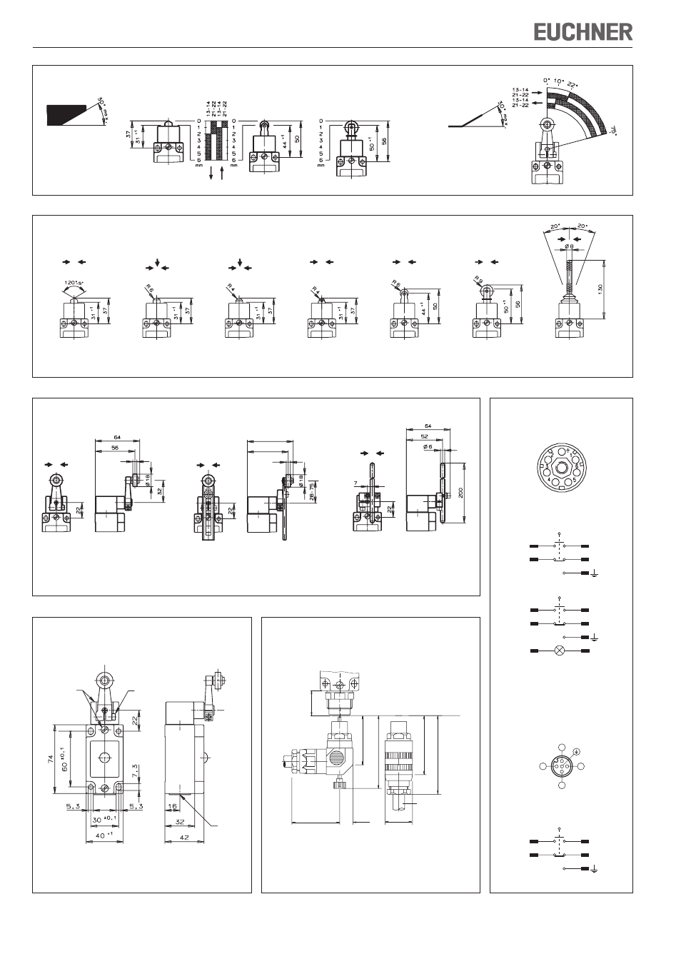
Figure 6: Actuator and approach directions
Figure 4: Travel diagrams
Figure 5: Actuator and approach directions
Figure 7: Dimension drawing NG1H.. with cable entry
Figure 8: Dimension drawing NG2... with plug connector
SR6
F
ree position
End position
End position
F
ree position
End position
F
ree position
DO = chisel plunger
WO = domed plunger
KO = ball plunger
RK = roller plunger
Roller plunger
RL = roller plunger
FO = spring actuator
RG = plastic roller
RS = steel roller
End position
F
ree position
Operating
point
End position
F
ree position
End position
F
ree position
End position
F
ree position
End position
F
ree position
End position
F
ree position
X
X
66
59
Roller arm switching on both sides
HB = plastic roller (measure X = 6 mm)
HS = steel roller (measure X = 5 mm)
Rod arm switching on both sides
SB = plastic rod
SM = aluminum rod
Adjustable roller arm
VB = plastic roller (measure X = 6 mm)
VS = steel roller (measure X = 5 mm)
Plug connector SR6
Pin assignment plug (Top view of
switch mounted connector)
Inser
te
d
Inser
te
d
M = 1,2 Nm
M = 1,2 Nm
M20x1,5
Plug connector SVM5
(M12, 5-pin)
Pin assignment plug (Top view of
switch mounted connector)
3
1
4
2
13
21
14
22
4
3
1
2
Pin assignment
ES 510
with LED indicator
3
1
4
2
13
21
14
22
5
6
3
1
4
2
13
21
14
22
Pin assignment
ES 510
Figure 9: Switching element and pin
assignment
Figure 9a
Figure 9b