Operating instructions position switch ng, Electrical connection, Correct use – EUCHNER NGxxx User Manual
Page 3: Incorrect use, Mounting, Setup, Service and inspection, Technical data
Operating Instructions Position Switch NG...
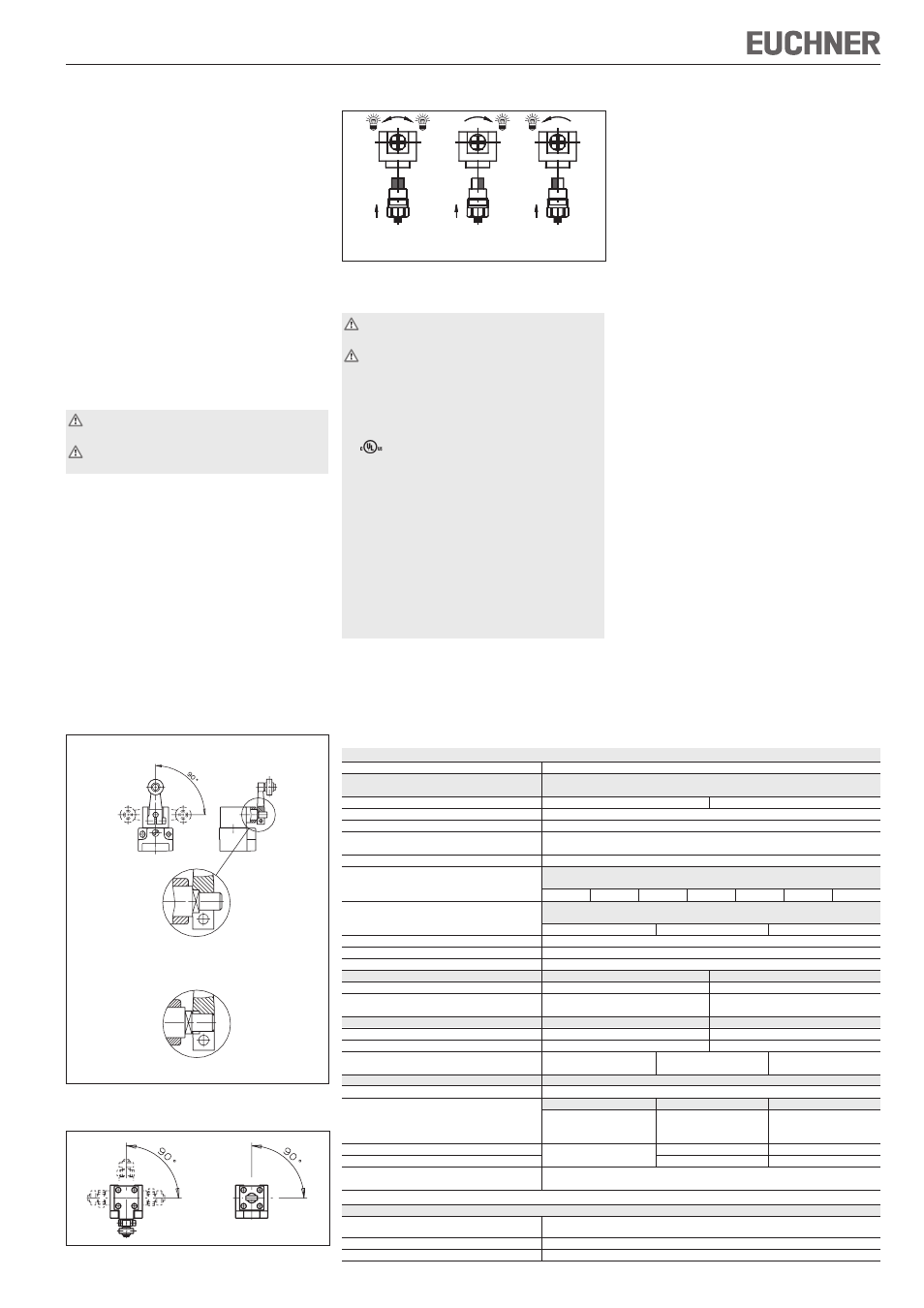
Switching direction change with lever arm actuation
Figure 3: Changing the switching direction
Electrical connection
Electrical connection must be performed only
by authorized personnel.
When choosing the insulation material and wire
for the connections, pay attention to the over-
temperature in the housing (depending on the
operating conditions)!
For NG2:
For use and applications as per the requirements
of
, a class 2 power supply or a class 2
transformer according to UL1310 or UL1585 must
be used.
Connection leads of position switches installed at
the application site must be separated from all
movable and permanently installed leads and non-
insulated active parts of other installation parts which
operate with a voltage of over 150 V, in such a way
that a constant clearance of 50.8 mm is observed.
This does not apply if the movable leads are equipped
with suitable insulation materials which possess an
identical voltage stability to the other relevant
installation parts or higher.
Correct use
Position switches series NG are used for positioning
and controlling machines and in industrial
installations.
The built-in switching element with snap-action
function has an NO and an NC contact with double
gap and electrically isolated switching bridge (direct
opening travel 2 x 0.6 mm)
Correct use includes compliance with the relevant
requirements for installation and operation, in
particular
EN 60 204-1, Safety of machinery. Electrical
equipment of machines. General requirements
EN 1050, Safety of machinery. Principles for risk
assessment.
Incorrect use
Position switches with switching element ES510
(snap-action switching element not positively dri-
ven) must not be used in safety circuits.
Mounting
Mounting must be performed only by authorized
personnel.
The position switches must not be used as a
mechanical stop.
The actuator (arm) can be positively mounted to
the actuating shaft.
The square drive on the actuator and actuating shaft
must engage with each other (see Figure 1a).
Continuously adjustable fastening is possible
(interference fit, see Figure 1b).
To ensure correct operation, the trip dog must
move the actuator at least 1 mm or 5° beyond the
switching point (see Figure 4 travel diagrams).
Position switches must be attached and, if
necessary, protected in such a way that predictable
damage can be avoided.
It must be ensured that position switches are
accessible for maintenance and function tests.
Adjustment options
Vertical actuator adjustment
Figure 1: Vertical actuator adjustment
Horizontal adjustment 4 x 90°
Figure 2: Horizontal adjustment
Left / right
Right
Left
switching
switching
switching
(standard position)
Version NG1... (cable entry)
Fit cable gland M20x1.5 with appropriate degree
of protection.
Conductor cross-section 0.34 ... 1.5 mm².
For pin assignment see Figure 9.
Tighten screws for connections to the switching
element to 1 Nm.
Check that the cable entry is sealed.
Close switch cover and tighten screws to 1.2 Nm.
Version NG2... (plug connector SR6)
Conductor cross-section 0.5 ... 1.5 mm².
For pin assignment see Figure 9a.
Version NG2... (plug connector M12/SVM5)
Conductor cross-section 0.34 mm².
For pin assignment see Figure 9b.
Setup
Function test
Actuate plunger or lever arm and check the
switching function.
Service and inspection
No servicing is required, but regular inspection
of the following is necessary to ensure trouble-free
long-term operation:
correct switching function
secure mounting of components
dirt and wear
sealing of cable entry
loose cable connections or
plug connectors.
Exclusion of liability under the following
conditions:
if the unit is not used for its intended purpose
non-compliance with safety regulations
installation and electrical connection not perfor-
med by authorized personnel
failure to perform functional checks.
The year of manufacture of the switch is indicated
in the production code.
Technical data
Parameters
Value
Housing material
Anodized die-cast alloy
NG1... Cable entry
NG2... Plug connector SR6
NG2... Plug connector M12/SVM5
Degree of protection according to IEC 60529
IP 67
IP 65
Mech. operating cycles
30 x 10
6
Ambient temperature
-25...+80°C
Degree of contamination
3 (industrial)
(external, according to EN 60947-1)
Installation position
Any
Approach speed max. [m/min]
HB
HS/
VB
VS
RK
WO/
RG/RS/
SB/SM
KO/DO
RL/FO
300
60
120
30
50
10
20
Approach speed, min.
HB/HS
WO/KO/RS/
FO/VB/
RK/RG/RL/DO
VS/SB/SM
0.1 m/min
0.01 m/min
0.5 m/min
Actuation frequency
7,000 / h
(HB/HS=10,000/h; FO=6,000/h)
Actuating force at 20 °C
15 N
Contact material
Silver alloy, gold flashed
NG1...
NG2...
Connection type
Screw terminals
Plug connector
Conductor cross-section (rigid/flexible)
0.34 ... 1.5 mm²,
SR6: 0.5 ... 1.5 mm²
0.34 ... 0.75 mm² with LED indicator
NG1...M / NG2...SR6
NG2...SVM5
Rated insulation voltage
U
i
= 250 V
U
i
= 50 V
Rated impulse withstand voltage
U
imp
= 2.5 kV
U
imp
= 2.0 kV
Indicator LED
L060
L110
L220
AC/DC 12 - 60 V
AC 110 V ±15%
AC 230 V ±15%
Rated data switching element ES510
Switching principle
Snap-action contact element
Utilization category according to IEC 60947-5-1
1)
Cable entry
Plug connector SR6
1)
Plug connector SVM5
AC-12
I
e
10 A
U
e
230 V
-
-
AC-15
I
e
6 A
U
e
230 V
I
e
6 A
U
e
230 V
I
e
4 A
U
e
30 V
DC-13
I
e
6 A
U
e
24 V
I
e
6 A
U
e
24 V
I
e
4 A
U
e
24 V
Short circuit protection (control circuit fuse)
1)
see
6 A gG
4 A gG
Conventional thermal current I
th
1)
Utilization category
6 A
4 A
Switching current, min. at
10 mA
Switching voltage
24 V DC
1) Limitation for NG2... at ambient temperature > 70 ... 80 °C:
NG2...SR6
Utilization category according
AC-15
Ie 2 A
Ue 230 V
to IEC 60947-5-1
DC-13
Ie 2 A
Ue 24 V
Short circuit protection (control circuit fuse)
2 A gG
Conventional thermal current I
th
2 A
Positive mounting 4 x 90°
Continuously adjustable interference fit mounting
Figure 1a
Figure 1b