Operating instructions enabling switch zsa/zsr, Figure 1: function of the switching elements – EUCHNER ZSR User Manual
Page 5
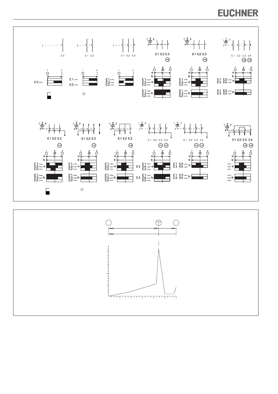
Operating Instructions Enabling Switch ZSA/ZSR
EUCHNER GmbH + Co. KG Kohlhammerstraße 16 D-70771 Leinfelden-Echterdingen Tel. +49/711/75 97-0 Fax +49/711/75 33 16 www.euchner.de [email protected]
F
F
F
F
F
F
+
+
+
+
ZSA1-1
ZSA1-2
ZSA1-3
ZSA2-1
Switching
element
Travel
diagram
Type
Figure 1: Function of the switching elements
WH BU GY
BN RD
BK
+
+
+
+
+
+
BN
BU
BK
GY
BN
BU
BK
GY
BN
BU
BK
GY
BN
BU
BK
GY
1
4
2
3
BN
BU
BK
GY
E1
E2
E3+E4
E1
E2
E3+E4
S3
S2
S1
BU
BN
BK
6
4
2
8
5
3
1
7
BN
RD
BK
WH
BU
GY
Contacts open
Contacts closed
T
Actuating point
ZSA2-2
ZSA2-4
ZSA2A1...
ZSR2A1...
ZSA2A2...
1)
ZSR2A2...
1)
ZSA2B2...
2)
ZSR2B2...
2)
ZSA2A3...
Switching
element
Travel
diagram
Type
ZSA2A4...
ZSA2B4...
1) With plug connector only for type ZSA2A2G05C-C1770
2) With plug connector only for type ZSA2B2G10B
Subject to technical modifications; no r
esponsibility is accepted for the accuracy of this information. © EUCHNER GmbH + Co. KG
092781-06-11/13 (translation of the original operating instructions)
E = Switching element
F = Spacer
Contacts open
Contacts closed
T
Actuating point E = Switching element
F = Spacer
Figure 2: Diagram of actuating force as a function of actuating travel
0
2
4
6
10
20
30
40
0
a
b
1
3
2
Actuating travel [mm]
Actuating for
ce appr
ox. [N]