2 technical data, As-i safety output relay with four standard inputs – EUCHNER AS-i Safety Output Relay with four standard inputs User Manual
Page 12
12
Subject to reasonable modifications due to technical advances
Id.-No.: 103573
Issue date - 28.5.2009
EUCHNER GmbH + Co. KG
Kohlhammerstraße 16 • D-70771 Leinfelden-Echterdingen
Tel. +49/711/75 97-0 • Fax. +49/711/753316
AS-i Safety Output Relay with four standard inputs
Product Description
4.2
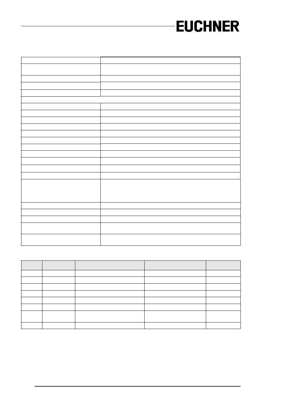
Technical Data
Inputs
3 standard inputs + 1 EDM
Outputs
1 relay
3 A, 24 V, DC-13 or 3 A, 230 V, AC-15 respectively
AS-i profile
S.7.A.E
ID1 Code
5
hex
(default), user changeable
External device monitoring (EDM)
Supplied from AS-i, about 24 V, about 10 mA
Displays
3 LEDs yellow (I 1, I 2, I 3)
Status input I1, I2, I3
1 LED yellow (1.Y1)
Status EDM input 1.Y1
LED green (PWR)
AS-i power supply
LED red (FAULT)
AS-i error LED
LED yellow (OUT)
See table for flashing LED pattern "Device colors"
LED red (ALARM)
PLC signals alarm
Operational current
< 200 mA
Supply power for sensors
90 mA
Operational current
AS-i (30 V
DC
)
Over-voltage category
3 for operating voltage 300 V
AC
acc. to VDE 0110 part 1
Voltage isolation
≥ 6 kV
Utilized standards
EN 954-1 Cat 4
IEC 61 508 SIL 3
EN 13849-1:2006/PLe Cat 4
EN IEC 6 2061 SIL 3
Housing
DIN rail mountable housing
Ambient operating temperature
0°C ... +55 °C
Storage temperature
-25°C ... +85 °C
Dimensions
(length/ width/ height in mm)
114 / 22,5 / 99
Protection category according to
DIN EN 60 529
Housing IP20
Device Colors
Value
Color
Description
State change
LED "Out"
0
green
Output on
on
1
green flashing
–
–
2
yellow
Error lock
Auxiliary signal 2
1 Hz
3
yellow flashing
–
–
4
red
Output off
off
5
red flashing
Waiting for error unlock signal
Auxiliary signal 1
8 Hz
6
gray
Internal error, for instance "fatal
error"
Only through turning power "on"
on the device
all LEDs are
flashing
7
green/yellow
Output released but not turned on
Switched "on" by setting O1
off