Combination options – EUCHNER CMS(01/13) User Manual
Page 6
Operating Instructions Read Heads/Actuators for Evaluation Units CMS
EUCHNER GmbH + Co. KG Kohlhammerstraße 16 D-70771 Leinfelden-Echterdingen Tel. +49 711 7597-0 Fax +49 711 753316 [email protected] www.euchner.de
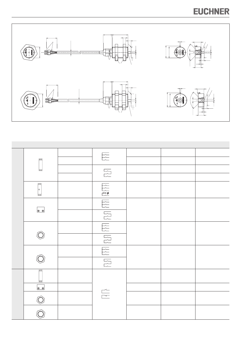
Figure 3: Dimension drawings for read heads CMS-R-C.. / CMS-R-E..
Dimension drawings for actuators CMS-M-C. / CMS-M-E.
Actuator CMS-M-E.
2
∅
30
32
,6
90
°
S
ao
2,
5
2,
5
∅
5,
5
2,5
13
15
Active face
Read head
Center of
fset m
at s = 3 mm
M
30
x1
,5
42
36
20
S
ao
2,
5
2,
5
8
ca
.
5,
8
∅
0,34 mm²
R1
SW40
SW15
Center of
fset m
at s = 3 mm
Actuator
Active face
Read head CMS-R-E..
2
∅
25
27
,5
90
°
S
ao
2,
5
2,
5
∅
5,
5
2,5
13,4
15
Center of
fset m
at s = 3 mm
Read head
Active face
Actuator CMS-M-C.
M
25
x1
,5
42
36
20
S
ao
2,
5
2,
5
6
ca
.
5,
8
∅
0,34 mm²
R1
SW15
SW32
Actuator
Active face
Center of
fset m
at s = 3 mm
Read head CMS-R-C..
Combination options
Design
Read head
Circuit diagram
not actuated
1)
Actuator
Assured switch-on distance
s
ao
[mm]
2)
Assured switch-off distance
s
ar
[mm]
Evaluation units
CMS-E-AR
CMS-R-AXD
BN
BK (YE)
WH
BU (GN)
CMS-M-AB
6
18
CMS-R-AXE
CMS-M-AG
18
34
CMS-R-AXF
BN
WH
CMS-M-AB
6
18
CMS-R-AXG
CMS-M-AG
18
34
3)
CMS-R-AXR
BN
BK (YE)
WH
PK
GY
BU (GN)
Rv
CMS-M-AI
9
(7)
4)
23
(15)
4)
CMS-R-BXO
BN
BK (YE)
WH
BU (GN)
CMS-M-BH
6
17
CMS-R-BXP
BN
WH
M25
CMS-R-CXA
BN
BK (YE)
WH
BU (GN)
CMS-M-CA
7
16
CMS-R-CXB
BN
WH
M30
CMS-R-EXL
BN
BK (YE)
WH
BU (GN)
CMS-M-EF
7
16
CMS-R-EXN
BN
WH
Evaluation units
CMS-E-BR, CMS-E-ER and CMS-E-FR
CMS-R-AXH
5)
BN
WH
BK (YE)
BU (GN)
CMS-M-AC
6
31
CMS-R-BXI
CMS-M-BD
3
12
M25
CMS-R-CXC
CMS-M-CA
6
14
M30
CMS-R-EXM
CMS-M-EF
6
17
1) Old conductor coloring in brackets.
2) There must be no ferromagnetic material in the vicinity of the read head or the actuator. All data refer to the frontal approach direction and a center offset of m = 0.
3) The LED for the contact status indication has an internal series resistor of 1.5 kΩ.
4) Operating distance for contact status indication and LED.
5) The minimum switching distance S
omin
between read head and actuator is 1 mm. If the distance is less than this, the evaluation unit changes to the fault state.