Kombinationsmöglichkeiten – EUCHNER CMS(01/13) User Manual
Page 3
Betriebsanleitung Leseköpfe/Betätiger für Auswertegeräte CMS
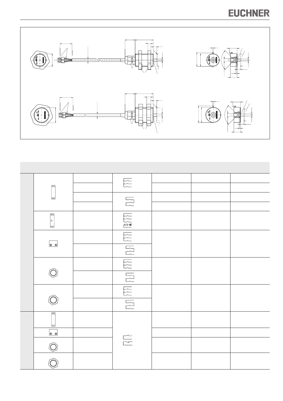
Bild 3: Maßzeichnungen Leseköpfe CMS-R-C.. / CMS-R-E..
Maßzeichnungen Betätiger CMS-M-C. / CMS-M-E.
Betätiger CMS-M-E.
2
∅
30
32
,6
90
°
S
ao
2,
5
2,
5
∅
5,
5
2,5
13
15
aktive Fläche
Lesekopf
M
itt
en
ve
rs
at
z
m
be
i s
=
3
m
m
M
30
x1
,5
42
36
20
S
ao
2,
5
2,
5
8
ca
.
5,
8
∅
0,34 mm²
R1
SW40
SW15
M
itt
en
ve
rs
at
z
m
be
i s
=
3
m
m
Betätiger
aktive Fläche
Lesekopf CMS-R-E..
2
∅
25
27
,5
90
°
S
ao
2,
5
2,
5
∅
5,
5
2,5
13,4
15
M
itt
en
ve
rs
at
z
m
be
i s
=
3
m
m
Lesekopf
aktive Fläche
Betätiger CMS-M-C.
M
25
x1
,5
42
36
20
S
ao
2,
5
2,
5
6
ca
.
5,
8
∅
0,34 mm²
R1
SW15
SW32
Betätiger
aktive Fläche
M
itt
en
ve
rs
at
z
m
be
i s
=
3
m
m
Lesekopf CMS-R-C..
Kombinationsmöglichkeiten
Bauform
Lesekopf
Schaltbild
nicht betätigt
1)
Betätiger
Gesicherter
Einschaltabstand
s
ao
[mm]
2)
Gesicherter
Ausschaltabstand
s
ar
[mm]
Au
sw
er
te
ge
rä
te
C
M
S-
E-
AR
CMS-R-AXD
BN
BK (YE)
WH
BU (GN)
CMS-M-AB
6
18
CMS-R-AXE
CMS-M-AG
18
34
CMS-R-AXF
BN
WH
CMS-M-AB
6
18
CMS-R-AXG
CMS-M-AG
18
34
3)
CMS-R-AXR
BN
BK (YE)
WH
PK
GY
BU (GN)
Rv
CMS-M-AI
9
(7)
4)
23
(15)
4)
CMS-R-BXO
BN
BK (YE)
WH
BU (GN)
CMS-M-BH
6
17
CMS-R-BXP
BN
WH
M25
CMS-R-CXA
BN
BK (YE)
WH
BU (GN)
CMS-M-CA
7
16
CMS-R-CXB
BN
WH
M30
CMS-R-EXL
BN
BK (YE)
WH
BU (GN)
CMS-M-EF
7
16
CMS-R-EXN
BN
WH
Au
sw
er
te
ge
rä
te
C
M
S-
E-
BR
, C
M
S-
E-
ER
u
nd
C
M
S-
E-
FR
CMS-R-AXH
5)
BN
WH
BK (YE)
BU (GN)
CMS-M-AC
6
31
CMS-R-BXI
CMS-M-BD
3
12
M25
CMS-R-CXC
CMS-M-CA
6
14
M30
CMS-R-EXM
CMS-M-EF
6
17
1) Alte Adernfarbe in Klammern.
2) Es darf kein ferromagnetisches Material in der Nähe von Lesekopf oder Betätiger vorhanden sein. Alle Angaben bei stirnseitiger Anfahrrichtung gelten und Mittenversatz m = 0.
3) Die LED für die Kontaktzustandsanzeige besitzt einen internen Vorwiderstand von 1,5 kΩ.
4) Ansprechabstand für Kontaktzustandsanzeige und LED.
5) Der minimale Schaltabstand S
omin
zwischen Lesekopf und Betätiger beträgt 1 mm. Wird der Abstand unterschritten kann das Auswertegerät in den Fehlerzustand gehen.