Determining cable lengths using the example table – EUCHNER CES-AR-CL2-CH (Multicode) User Manual
Page 13
Operating Instructions Safety Switches CES-AR-C.2-CH
13
Determining cable lengths using the example table
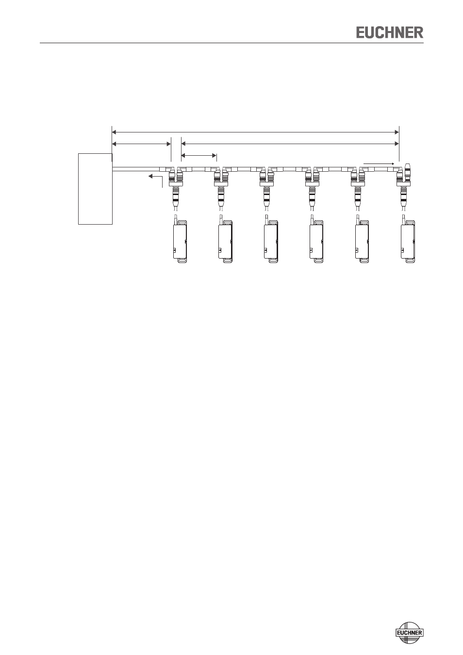
Example: 6 switches are to be used in series. Cabling with a length of 40 m is
routed from a safety relay in the control cabinet to the last switch (#6) (conduc-
tor cross-section 0.34 mm²). Cables with a length of 20 m each are connected
between the individual CES-AR safety switches.
Fig. 1: Circuit example with six CES-AR
A safety relay is connected downstream which consumes 75 mA at each of the
two safety inputs. This operates over the whole temperature range with a voltage
of 19.2 V (corresponds to 24 V -20%).
All the relevant values can now be determined using the example table:
1. Select the corresponding section in the column n (max. number of switches).
Here: 6 switches.
2. In column I
out
(possible output current per channel OA/OB), find a current
greater than or equal to 75 mA. Here: 100 mA.
¨
It is then possible to determine the maximum cable length from the last switch
(#6) to the control system from column l
1
. Here: a length of 50 m is permissible
with a conductor cross-section of 0.34 mm².
Result: The desired cable length l
1
of 40 m is below the permitted value from the
table. The overall length of the switch chain l
max
of 140 m is less than the maximum
value of 200 m.
¨
The planned application is therefore functional in this form.
CES-AR # 6
Sicherheits-
relais
Safety Relay
CES-AR # 5
CES-AR # 4
CES-AR # 3
CES-AR # 2
CES-AR # 1
STATE
DIA
STATE
DIA
STATE
DIA
STATE
DIA
STATE
DIA
STATE
DIA
l
1
= 40 m
l
2
= 5 x 20 m
l
max
= 140 m
l
n
= 20 m
u
n
= min. 19,2 V
i
out
= min. 75 mA