Typical system times, Dimension drawings – EUCHNER CES-I-AP-M-C04 (Multicode) User Manual
Page 20
Operating Instructions Safety Switch CES-I-AP-M-C04
20
Typical system times
Ready delay: After switching on, the unit carries out a self-test for 0.5 s. The
system is ready for operation only after this time.
Switch-on time of safety outputs: The max. reaction time from the moment
when the actuator is at the operating distance (safety door closed) to the moment
when the safety outputs switch on T
on
is 300 ms.
Risk time according to EN 60947-5-3: If an actuator moves outside the
operating distance, the safety outputs FO1A and FO1B are deactivated after a
maximum of 260 ms.
Difference time: The safety outputs FO1A and FO1B switch with a slight delay
in relation to each other. They have the same signal state at the latest after a dif-
ference time of 10 ms.
Test pulses at the safety outputs: The device generates its own clock signal on
the output lines FO1A/FO1B. A downstream control system must tolerate these
test pulses, which may last up to 0.3 ms (applies for a load with C < 30 nF and
R < 20 kW).
This can usually be set up in the control systems by parameter assignment. If
parameter assignment is not possible for your control system or if shorter test
pulses are required, please contact our support organization.
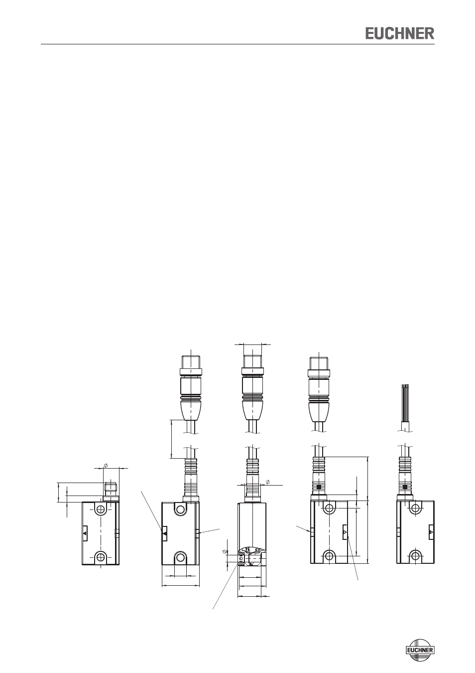
Dimension drawings
10,6
M12x1
42
4,
1
29
,2
25
8
32
10,6
4,
1
12
,9
ca. 100/220
15,5
14,5
4,
8
18
Active face
LEDs
Active
face
LEDs
With M8 plug connector
Connection cable with
flying lead
Connection cable with M12 plug connector
Rubber support
(included)
With rubber support