Setup, Led indicators, Initial setup – EUCHNER CES-I-AP-M-C04 (Multicode) User Manual
Page 16: Setup 16 led indicators
Operating Instructions Safety Switch CES-I-AP-M-C04
16
Setup
LED indicators
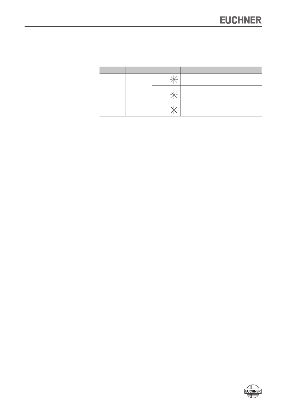
LED
Color
State
Significance
STATE
green
illumi-
nated
Normal operation: Door closed
flashing
- Power Up
- Door open
- Actuator in the limit range
(refer to the status table for further signal functions)
DIA
red
illumi-
nated
- Internal electronics fault
- Fault at the inputs/outputs
Initial setup
1. Apply operating voltage to the safety switch.
¨
The red LED flashes briefly
A self-test is performed during this time. After this, the green LED flashes
cyclically one time and signals that it is in standby state.
2. Move actuator to the read head (observe distance < S
ao
).
¨
The green LED illuminates continuously and indicates the detection of the
actuator.
If the green LED is flashing quickly, the actuator is in the boundary area. In
this case the safety guard must be re-adjusted such that the actuator is com-
pletely in the read area.
- N1A Single hole fixing limit switch (12 pages)
- NZ Safety switch (12 pages)
- NZ.VZ (15 pages)
- NZ.VZ-xxxVS (16 pages)
- TZxxxAS1 (16 pages)
- TZxxx (20 pages)
- NXxxx (12 pages)
- TXxxx (12 pages)
- SGAxxx (12 pages)
- STAxxx (15 pages)
- STA-TWxxx (Twin) (15 pages)
- NMxxAV/AL (8 pages)
- NMxxWO/RB (12 pages)
- NMxxKB (12 pages)
- NMxxHB (12 pages)
- NMxxAK/AG (8 pages)
- NMxxVZ (15 pages)
- NP (12 pages)
- GPxxx (12 pages)
- TPxxx (12 pages)
- SGPxxx (12 pages)
- SGP-TWxxx (Twin) (12 pages)
- STP-TWxxx (Twin) (15 pages)
- STPxxx (15 pages)
- STP-BIxxx (12 pages)
- STMxxx (12 pages)
- NQxxVZ (8 pages)
- TQxxx (12 pages)
- TKxxx (12 pages)
- ESH (8 pages)
- Hinge ESH Re-adjustable (8 pages)
- MGB-AR (14 pages)
- MGB-L1-xxxARx-xxx (38 pages)
- MGB-L0-xxxARx-xxx (36 pages)
- MGB-LxxB-PNx-xxx (PROFINET) with Data Structure Type B (44 pages)
- MGB-LxxB-PNA-xxx (PROFINET) with Data Structure Type A (36 pages)
- CES-A-ABA-01 (Unicode) (42 pages)
- CES-Axxx (5 pages)
- CES-A-AEA-02B (Unicode) (44 pages)
- CES-A-UBA-01 (Multicode) (40 pages)
- CES-A-UEA-02B (Multicode) (44 pages)
- CES-AZ-ABS-01B (Unicode) (40 pages)
- CES-AZ-UBS-01B (Multicode) (38 pages)
- CES-AZ-AES-xxx (Unicode) (54 pages)
- CES-AZ-UES-xxx (Multicode) (56 pages)