Connection – EUCHNER CES-I-AP-M-C04 (Multicode) User Manual
Page 14
Operating Instructions Safety Switch CES-I-AP-M-C04
14
Connection
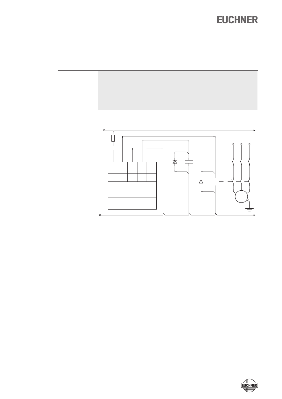
Connect the device as shown in Figure 3. The OD output can also be connected
to a control system as a monitoring output.
Important!
The subsystem CES-I-AP complies with PL e in accordance with EN 13849-1. To
integrate the subsystem in a category 3 or 4 structure, it is necessary to monitor
the downstream load (the feedback loop must be monitored).
These examples show only an excerpt that is relevant for connection of the CES
system. The example illustrated here does not show complete system planning.
The user is responsible for safe integration in the overall system.
GND
DC 24 V
-F1
CES-I-AP-...-SB-...
UB
1
FO1A
2
FO1B
4
M12 plug-connector
(5-pin)
OD
5
0V UB
3
-V1
-K1
-V2
-K2
L1
M
3
~
-M1
L2
L3
Figure 3: Connection example CES-I-AP-M-C04-SB
- N1A Single hole fixing limit switch (12 pages)
- NZ Safety switch (12 pages)
- NZ.VZ (15 pages)
- NZ.VZ-xxxVS (16 pages)
- TZxxxAS1 (16 pages)
- TZxxx (20 pages)
- NXxxx (12 pages)
- TXxxx (12 pages)
- SGAxxx (12 pages)
- STAxxx (15 pages)
- STA-TWxxx (Twin) (15 pages)
- NMxxAV/AL (8 pages)
- NMxxWO/RB (12 pages)
- NMxxKB (12 pages)
- NMxxHB (12 pages)
- NMxxAK/AG (8 pages)
- NMxxVZ (15 pages)
- NP (12 pages)
- GPxxx (12 pages)
- TPxxx (12 pages)
- SGPxxx (12 pages)
- SGP-TWxxx (Twin) (12 pages)
- STP-TWxxx (Twin) (15 pages)
- STPxxx (15 pages)
- STP-BIxxx (12 pages)
- STMxxx (12 pages)
- NQxxVZ (8 pages)
- TQxxx (12 pages)
- TKxxx (12 pages)
- ESH (8 pages)
- Hinge ESH Re-adjustable (8 pages)
- MGB-AR (14 pages)
- MGB-L1-xxxARx-xxx (38 pages)
- MGB-L0-xxxARx-xxx (36 pages)
- MGB-LxxB-PNx-xxx (PROFINET) with Data Structure Type B (44 pages)
- MGB-LxxB-PNA-xxx (PROFINET) with Data Structure Type A (36 pages)
- CES-A-ABA-01 (Unicode) (42 pages)
- CES-Axxx (5 pages)
- CES-A-AEA-02B (Unicode) (44 pages)
- CES-A-UBA-01 (Multicode) (40 pages)
- CES-A-UEA-02B (Multicode) (44 pages)
- CES-AZ-ABS-01B (Unicode) (40 pages)
- CES-AZ-UBS-01B (Multicode) (38 pages)
- CES-AZ-AES-xxx (Unicode) (54 pages)
- CES-AZ-UES-xxx (Multicode) (56 pages)