Ces-i-ap-...-.sk-... with m8 plug connector, 4-pin, Connection cable with m12 plug connector, 5-pin – EUCHNER CES-I-AP-M-C04 (Multicode) User Manual
Page 13
Operating Instructions Safety Switch CES-I-AP-M-C04
13
Connector assignment and wire color for safety
switch CES-I-AP-M-C04
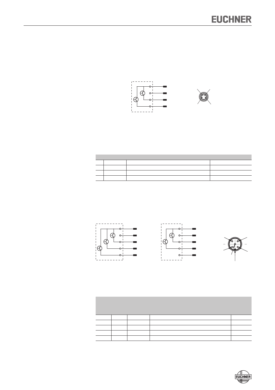
CES-I-AP-...-.SK-... with M8 plug connector, 4-pin
Figure 1: Connector assignment of M8 plug connector
Pin Designation
Description
Wire color
1
UB
Power supply, DC 24 V
BN
2
FO1A
Safety output, channel 1
WH
3
0V
Ground, DC 0 V
BU
4
FO1B
Safety output, channel 2
BK
Connection cable with M12 plug connector, 5-pin
Figure 2: Connector assignment, connection cable with M12 plug connector
Pin
Designation
Description
Wire color
5-pin
5-pin
pin 5
not used
1
1
UB
Power supply, DC 24 V
BN
2
2
FO1A
Safety output, channel 1
WH
3
3
0V
Ground, DC 0 V
BU
4
4
FO1B
Safety output, channel 2
BK
5
-
OD
Monitoring output
GY
View on the connection side of the safety switch
X1.1
X1.3
X1.2
X1.4
X1.5
+UB
0V
FO1A
FO1B
n.c.
4
1
5
2
3
X1.1
X1.3
X1.2
X1.4
X1.5
+UB
0V
FO1A
FO1B
OD
Coding lug
CES-I-AP-...-.SB-...
5-pin
CES-I-AP-...-.SI-...
5-pin,
pin 5 not used
X1.1
X1.3
X1.2
X1.4
+UB
0V
FO1A
FO1B
4
2
1
3
View on the connection side of the safety switch