Block diagram ces-a-aea-04b, Read heads coded actuators – EUCHNER CES-A-AEA-04B (Unicode) User Manual
Page 8
Operating Instructions Safety System CES-A-AEA-02B/CES-A-AEA-04B
8
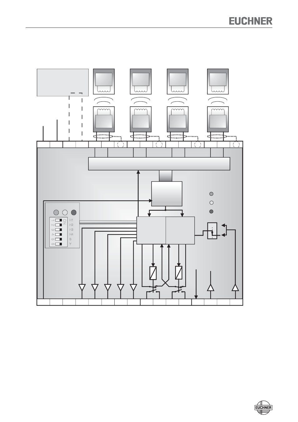
Block diagram CES-A-AEA-04B
Trans-
ponder
Trans-
ponder
Trans-
ponder
Trans-
ponder
Kopf 1
Kopf 2
Kopf
opf 4
A
B
C
D
0 V
0V
S
H11
H31
H21
H41
H12
H32
H22
H42
SH1
SH3
SH2
SH4
O3
O4
14
13
23
24
Y2
Demodulator
Filter
Verstärker
Komparat or
KA
KB
K
( 1 aus 4
TST
0V
J2
J1
O1
O2
DIA
23
Y1
24
Y2
+24 V
KA
KB
CPU-A
(Typ 1)
LED
STATE
OUT
DIA
Star t
Start
CPU-B
(Typ 2)
STATE OUT DIA
UB
Y
S
H4
H3
H2
H1
ON
1
2
3
4
5
6
Head selection
Demodulator
Filter
Amplifier
Comparator
CPU-A
(type 1)
Head -RF - mulitplexer
(1 of 4)
CPU-B
CPU-B
CPU-A
CPU-A
CPU-B
(type 2)
DIP switch
Activation of the
teach-in operation with
jumper
on J1, J2
Read heads
Coded
actuators
Trans-
ponder
Head 1
DC
+ 24 V
Operating
voltage
Trans-
ponder
Trans-
ponder
Trans-
ponder
Head 2
Head 3
Head 4
+UB, 0 V
Power supply
J1, J2
Short circuit bridge for teach-in operation
H11/H12...H41/H42 Connection for read heads 1 ... 4
SH1 ...SH4
Shield
TST
Test input (see „Self-test with test input TST“ page 17)
O1 ... O4
Semiconductor monitoring outputs
DIA Diagnostics
output
13, 14
Relay contact A connection, safety relay enable
23, 24
Relay contact B connection, safety relay enable
Y1, Y2
Feedback loop
S
Start button connection (monitoring of the falling edge)