Terminate wiring, Interface series – ETC Unison Heritage Contact and Fader Interface User Manual
Page 3
E T C I n s t a l l a t i o n G u i d e
Interface Series
Unison
®
Heritage Contact and Fader Interface
Page 3 of 4
Electronic Theatre Controls, Inc.
Terminate Wiring
Locate the termination kit shipped with the Interface packaging. This kit
includes a LinkPower pigtail, an Auxiliary Power pigtail and all required
connectors for use during installation.
Step 1:
Terminate and connect LinkPower. LinkPower is topology
free and polarity independent. You may install LinkPower
in any combination of bus, loop, star or home-run.
a: Locate the LinkPower pigtail and two WAGO cage
clamp connectors from the termination kit.
b: Strip 3/8” (9-10mm) from the ends of each LinkPower
wire (both the provided pigtail and installed LinkPower
wire).
c: Use the WAGO cage clamp connector to connect the installed control wire to the
connectorized pigtail wires provided. Open the terminal levers on the WAGO
connector and insert the installed (typically black) Belden 8471 LinkPower wire and
the black lead from the LinkPower pigtail into the terminals.
d: Close the levers onto the wires.
e: Repeat for the installed (typically white) Belden 8471 LinkPower wire and remaining
pigtail wire using a new WAGO connector.
f: Install the LinkPower connector to J2 (NET) on the control board.
Step 2:
Terminate and connect Auxiliary Power (24 Vdc) wiring.
a: Locate the Auxiliary Power pigtail and two WAGO cage clamp connectors from the
termination kit.
b: Strip 3/8” (9-10mm) from the ends of each Auxiliary wire (both the provided pigtail and
installed wire).
c: Use the WAGO cage clamp connector to connect the installed power wire to the
connectorized pigtail wires provided. Open the terminal levers on the WAGO
connector and insert the installed (typically black) 16 AWG (1.5mm
2
) Auxiliary Power
wire and the black lead from the pigtail into the terminals.
d: Close the levers onto the wires.
e: Repeat for the installed (typically red) 16 AWG (1.5mm
2
) Auxiliary power wire and
remaining pigtail wire using a new WAGO connector.
f: Install the Auxiliary connector, labeled “Power” (location J5 for Contact Interface and
J7 for the Fader Interface) on the control board.
Step 3:
Terminate the ESD drain (ground) wire.
a: Strip 7/16” (11mm) from the end of the ground wire.
b: Loosen the terminal screw on a green/yellow terminal block. The green/yellow
terminal blocks are located at either end of the terminal strip. All field terminations
should be made to the right side of the terminal strip.
c: Insert the ground wire and tighten the screw onto the wire.
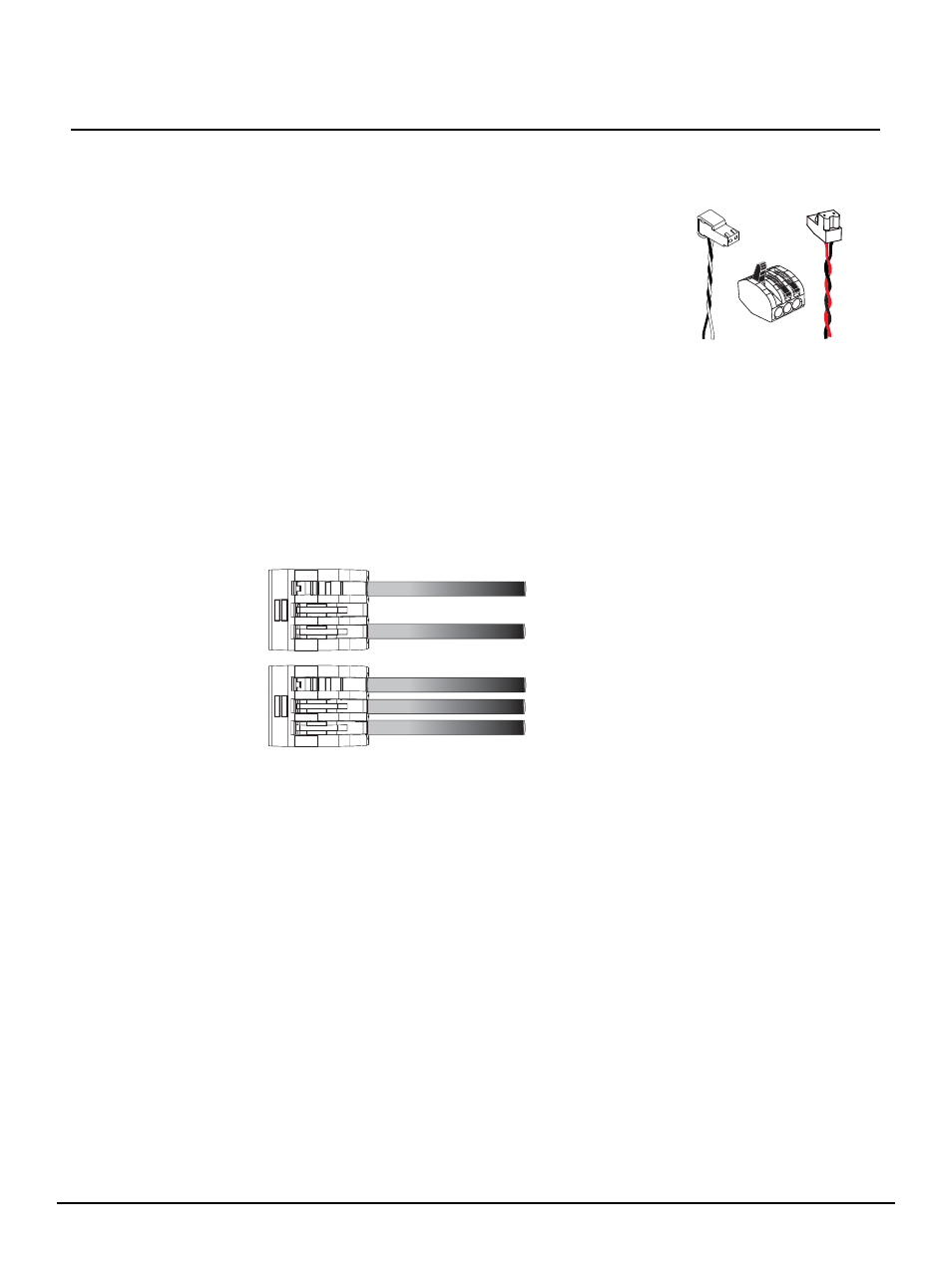
LinkPower
pigtail
Auxiliary
Power pigtail
WAGO
topology of a single
station installation
topology of multiple
stations installed in
series
installed control wire
installed control wire to next station
pigtail wire
installed control wire
pigtail wire