Light sensor – ETC Unison Paradigm Light Sensor User Manual
Page 4
E T C I n s t a l l a t i o n G u i d e
Light Sensor
Unison Paradigm Light Sensor Installation Guide
Page 4 of 8
Electronic Theatre Controls, Inc.
Step 2:If you are installing the controller in series with other sensors, sensor
controllers, or stations (continuing the data run), use the provided LinkConnect
pigtail, ESD ground pigtail and WAGO connectors to make the terminations. If
you are not continuing the data run, proceed to step 4.
Step 3:If you are installing the primary and/or optional second light sensor
remotely from the controller, reference
"Installing the Light Sensors Remotely
on page 6, then return to these instructions. If you are not remoting
a light sensor, proceed to step 4.
Step 4:Orient the smooth side of the mounting plate to the junction box and pull each
run of Belden 8471 (LON and remote sensor wires) and the 14 AWG (2.5mm
2
)
ESD drain wire from the junction box through the provided holes near the
center of the mounting plate.
Step 5:Secure the mounting plate to the junction box using the screws provided (both
short and long screws are included for convenience).
Step 6:Strip each wire 5/16” (8mm) and terminate the white, black, and green (ground)
wires to the LON terminal block located on the sensor control board. Torque
each termination to 3.1-3.5 in-lb.
a: Terminate the white incoming wire to terminal A.
b: Terminate the black incoming wire to terminal B.
c: Terminate the green wire to the labeled ground terminal.
Step 7:If the primary or an optional second light sensor is installed remotely
from the controller, reference
"Installing the Light Sensors Remotely (optional)"
on page 6 for termination instructions, then return to these instructions.
Otherwise, proceed to step 8.
Step 8:Attach the sensor to the mounting plate by aligning the tabs on the sensor with
the slots on the mounting plate, then twist clockwise until the two are locked
into place.
N o t e :
Primary Sensor and Optional Sensor wires should terminate directly to
the terminals located on the controller. See
install
ed control
wire
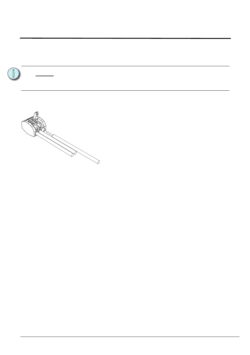
installed control wire to next stati
on
sensor pigtail
a: Strip 3/16” (5mm) of insulation from each installed LON
wire.
b: Open the three terminal levers on a WAGO connector
and insert the installed (typically black) Belden 8471
LinkConnect wire, the black lead from the sensor pigtail,
and the continuing Belden 8471 (typically black) wire into
the terminals.
c: Close the levers onto the wires.
d: Repeat the above for the installed (typically white)
Belden 8471 LinkConnect wire and the remaining pigtail
from the sensor, as well as the ESD ground wires using
a new WAGO connector and the ground pigtail for each
termination type.