Remoting the light sensor, Installation environment, Parts and supplies – ETC Unison Paradigm Light Sensor User Manual
Page 2: Light sensor
E T C I n s t a l l a t i o n G u i d e
Light Sensor
Unison Paradigm Light Sensor Installation Guide
Page 2 of 8
Electronic Theatre Controls, Inc.
All control wiring should be installed and terminated by a qualified installer, should
follow standard wiring installation practices, and meet local codes. Leave
approximately 10 inches (254mm) of wiring in the junction box or tied back in the
ceiling to allow for wiring connections and future service needs.
Remoting the Light Sensor
The Paradigm Light Sensor Controller provides termination for up to two light
sensors. Each light sensor must be separately wired to the controller using no more
than 1000 feet (304m) of 16 AWG wire total per controller. These wire runs must
remain separate from LinkConnect wiring. ETC recommends using Belden 8471 (or
equivalent) wire.
Installation Environment
The Paradigm Light Sensor Controller is intended for installation to a finished ceiling
surface, soft ceiling tile, attached to a round fixture junction box or single-gang RACO
switch box. The controller operates in ambient temperatures of 0°C to 40°C, non-
condensing humidity.
The Paradigm Light Sensor can be mounted directly in the controller, installed to a
1/2” conduit knockout or installed into a soft ceiling tile using the provided light
sensor thread extender. The light sensor can be installed outdoors when mounted to
a weatherproof enclosure. The sensor in this weatherproof installation scenario
operates in ambient temperatures of -25°C to 70°C.
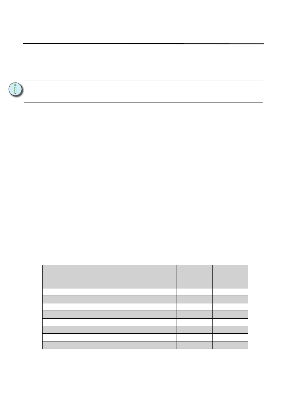
Parts and Supplies
The following parts and supplies are included with the specific Paradigm Light Sensor
assembly ordered:
N o t e :
ETC requires that all stations be grounded by using a 14 AWG (2.5mm
2
)
ESD drain wire.
Parts and Supplies
Light Sensor
complete
unit (P-LS)
Light Sensor
only
(P-LSH)
Light Sensor
Controller
only (P-LSC)
soft ceiling tile adaptor
X
X
LinkConnect and ground wire pigtails
X
X
light sensor thread extender
X
X
3 position WAGO connectors
X
X
2 position WAGO connectors
X
1 each nuts and washers 3/4” and 1”
X
X
2 each screws 6-32 x 3/4” and 1 3/4”
X
X
blank sensor head
X
X