Safety cable, Installation, Desire series d40/d60 xti – ETC Desire Series XTI User Manual
Page 3
E T C I n s t a l l a t i o n G u i d e
Desire Series D40/D60 XTI
D40/D60 XTI
Page 3 of 4
Electronic Theatre Controls, Inc.
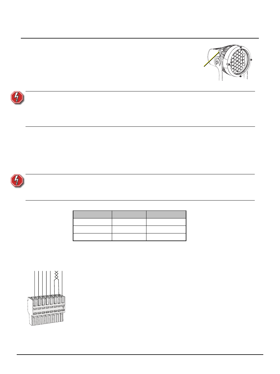
Safety Cable
The safety cable should be attached to the fixture housing and
wrapped around the hanging or mounting structure. An
attachment loop is provided on the fixture housing. Leave as
little slack as possible in the safety cable to avoid the cable
catching the yoke of the fixture.
Installation
Step 1:
Prepare the installation location, conforming to the
specification on
.
When using an ETC Desire XTI mounting accessory, reference the installation
instructions provided.
Step 2:
Hang or mount the fixture.
• Use the center hole in the yoke when frequent focusing adjustments are necessary.
Use all three mounting holes when installed in permanent/fixed locations. The
elongated holes allow for small focus adjustments as needed.
Step 3:
Terminate the power input leads. Reference
Step 4:
Install the termination board into a voltage separated junction box. The termination board
is provided with double sided tape for easy installation. Reference
.
Step 5:
Terminate DMX/RDM input cable from the Desire XTI fixture to the termination board.
a: Cut the Desire XTI DMX/RDM input cable (if necessary) allowing enough slack for
positioning the fixture, terminations, and future service needs.
b: Route the cable through the strain relief of the voltage separated junction box (provided by
others).
c: Strip 3” (7.6cm) off the end of the cable jacket. Do not trim the braided shielding as this is
used for grounding to the termination board.
d: Peel the braided shielding back onto the cable jacket.
e: Remove the Insulation Displacement Connector (IDC) from the termination board (labeled
Desire XTI).
f:
Maintain the wire pair twist as close to the connector as possible and terminate the wires as
indicated in the graphic to the left. Do not strip the individual conductors.
g: Replace the connector to the termination board.
W A R N I N G :
Do not use this fixture with a damaged power input cable. If the power input
cable is damaged, it must be replaced.
Do not expose the interior of the fixture to moisture.
Do not stand in water while installing or servicing the fixture.
Failure to follow these warnings may result in serious injury or death.
W A R N I N G :
RISK OF DEATH BY ELECTRIC SHOCK! Check that power is off to the main
supply before proceeding with terminating power leads to the fixture.
De-energize the main feed and follow appropriate Lockout/Tagout procedures
as described in NFPA 70E.
Mains
Europe
North America
Line
Brown
Black
Neutral
Blue
White
Ground (Earth)
Green/Yellow
Green
Safety cable
attachment
Cat5 (or equivalent) wire
termination to IDC connector
W/B
L
U
W/
GRN
GR
N
BR
N
Data + W/ORG
Data -
ORG
Com W/BRN
BLU