Main and auxiliary feedback combinations – ElmoMC ExtrIQ Digital Servo Drives-Hawk User Manual
Page 40
Hawk Installation Guide
Installation
MAN-HAWIG (Ver. 1.401)
40
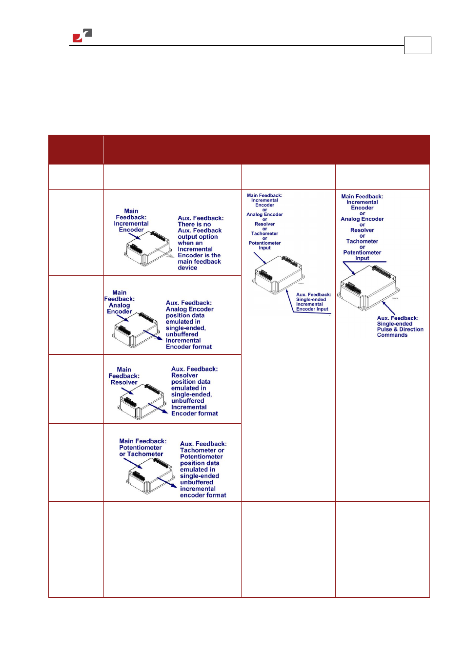
3.10.1. Main and Auxiliary Feedback Combinations
The Main Feedback is always used in motion control devices whereas Auxiliary Feedback is
often, but not always used. The Auxiliary Feedback connector on the Hawk has three bi-
directional pins (CHA, CHB and INDEX). When used in combination with Main Feedback, the
Auxiliary Feedback can be set, by software, as follows:
Main
Feedback
Auxiliary Feedback
Software
Setting
YA[4] = 4
(Aux. Feedback: output)
YA[4] = 2
(Aux. Feedback: input)
YA[4] = 0
(Aux. Feedback: input)
Incremental
Encoder Input
Interpolated
Analog
(Sin/Cos)
Encoder Input
Resolver
Input
Potentiometer
or
Tachometer
Input
Typical
Applications
Analog Encoder
applications where
position data is required in the
Encoder’s quadrature format.
Resolver applications where position
data is required in the Encoder’s
quadrature format.
Tachometer or potentiometer
applications where position data is
required in the Encoder’s quadrature
format.
Any application where two
feedbacks are used by the
drive.
The Auxiliary Feedback port
serves as an input for the
auxiliary incremental
encoder.
For applications such as
Follower, ECAM, or Dual
Loop.
Any application where two
feedbacks are used by the
drive.
The Auxiliary Feedback port
serves as an input for Pulse
& Direction Commands.