ElmoMC ExtrIQ Digital Servo Drives-Hawk User Manual
Page 31
Hawk Installation Guide
Installation
MAN-HAWIG (Ver. 1.401)
31
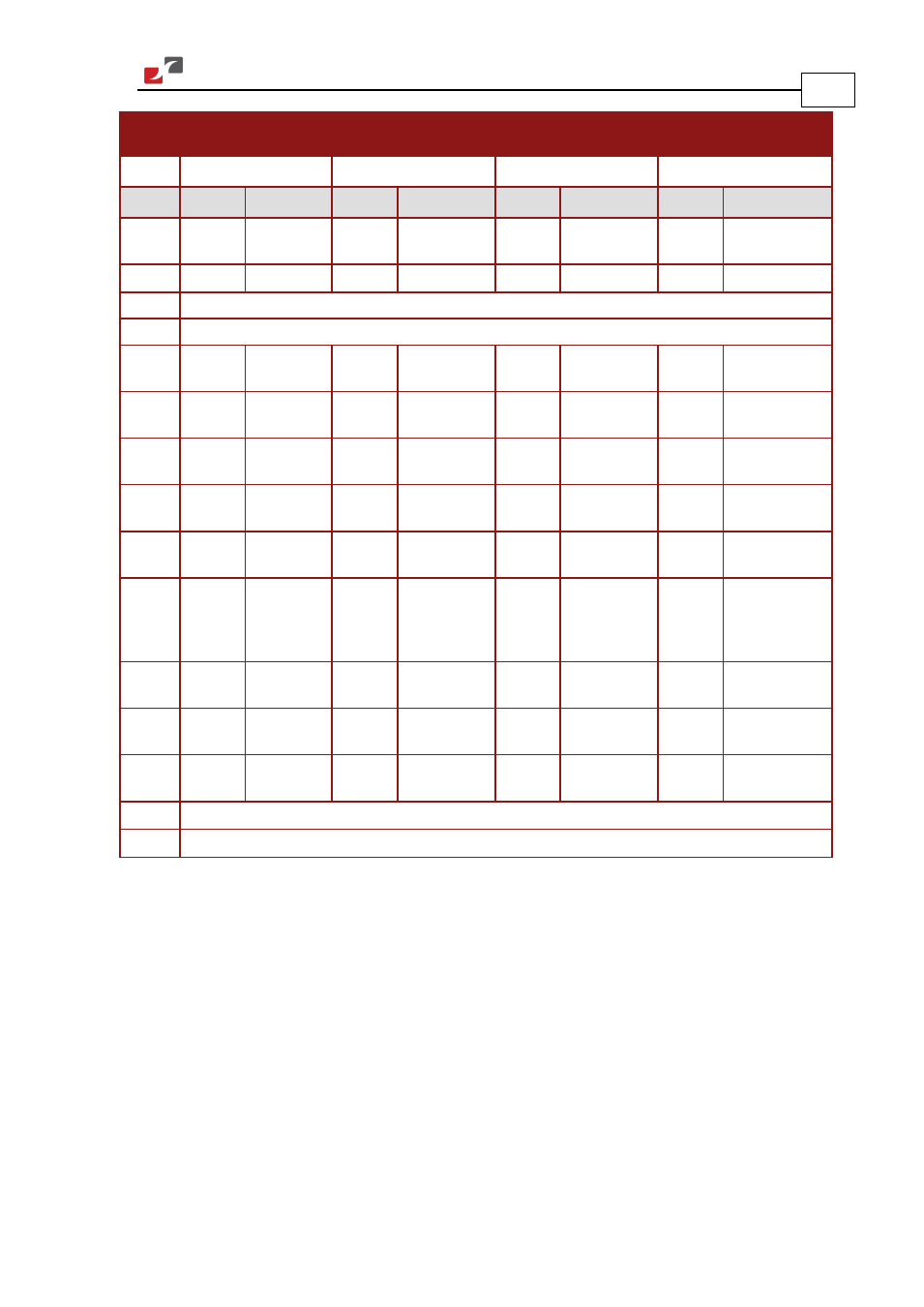
Incremental
Encoder
Interpolated
Analog Encoder
Resolver
Tachometer and
Potentiometer
HAW-
XX
/
YYY
_
HAW-
XX
/
YYY
I
HAW-
XX
/
YYY
R
HAW-
XX
/
YYY
T
Pin (J2) Signal Function Signal Function
Signal Function
Signal Function
1
+5V
Encoder/Hall
+5V supply
+5V
Encoder/Hall
+5V supply
+5V
Encoder/Hall
+5V supply
+5V
Encoder/Hall +5V
supply
2
SUPRET
Supply return SUPRET
Supply return
SUPRET
Supply return
SUPRET
Supply return
3
ANALIN+ is used for Analog Input
4
ANALIN- is used for Analog Input
5
CHA
Channel A
A+
Sine A
S1
Sine A
Tac 1+
Tacho Input 1
Pos. (20 V max)
6
CHA-
Channel A
complement
A-
Sine A
complement
S3
Sine A
complement
Tac 1-
Tacho Input 1
Neg. (20 V max)
7
CHB
Channel B
B+
Cosine B
S2
Cosine B
Tac 2+
Tacho Input 2
Pos. (50 V max)
8
CHB-
Channel B
complement
B-
Cosine B
complement
S4
Cosine B
complement
Tac 2-
Tacho Input 2
Neg. (50 V max)
9
INDEX
Index
R+
Reference
R1
Vref f=1/TS,
50 mA Max
POT
Potentiometer
Input (5 V Max)
10
INDEX-
Index
complement
R-
Reference
complement
R2
Vref
complement
f = 1/TS, 50 mA
Max
NC
-
11
HA
Hall sensor A
input
HA
-
NC
-
HA
Hall sensor A
input
12
HB
Hall sensor B
input
HB
-
NC
-
HB
Hall sensor B
input
13
HC
Hall sensor C
input
HC
-
NC
-
HC
Hall sensor C
input
14
LED_2_OUT (AOKLED cathode) is used for LED indication
15
LED_1_OUT (AOKLED anode) is used for LED indication
Table 3: Main Feedback Pin Assignments