ElmoMC SimplIQ Digital Servo Drives-Cello Installation Guide User Manual
Page 40
Cello Installation Guide
Installation
MAN-CELIG (Ver. 1.602)
40
3.4.7.3
Single-Ended Auxiliary Input Option on FEEDBACK B (YA[4]=2)
The Cello can be used as a slave by receiving the position data (on Port B1) of the master
encoder in Follower or ECAM mode. In this mode Port B2 provides differential buffered
auxiliary outputs for the next slave axis in Follower or ECAM mode.
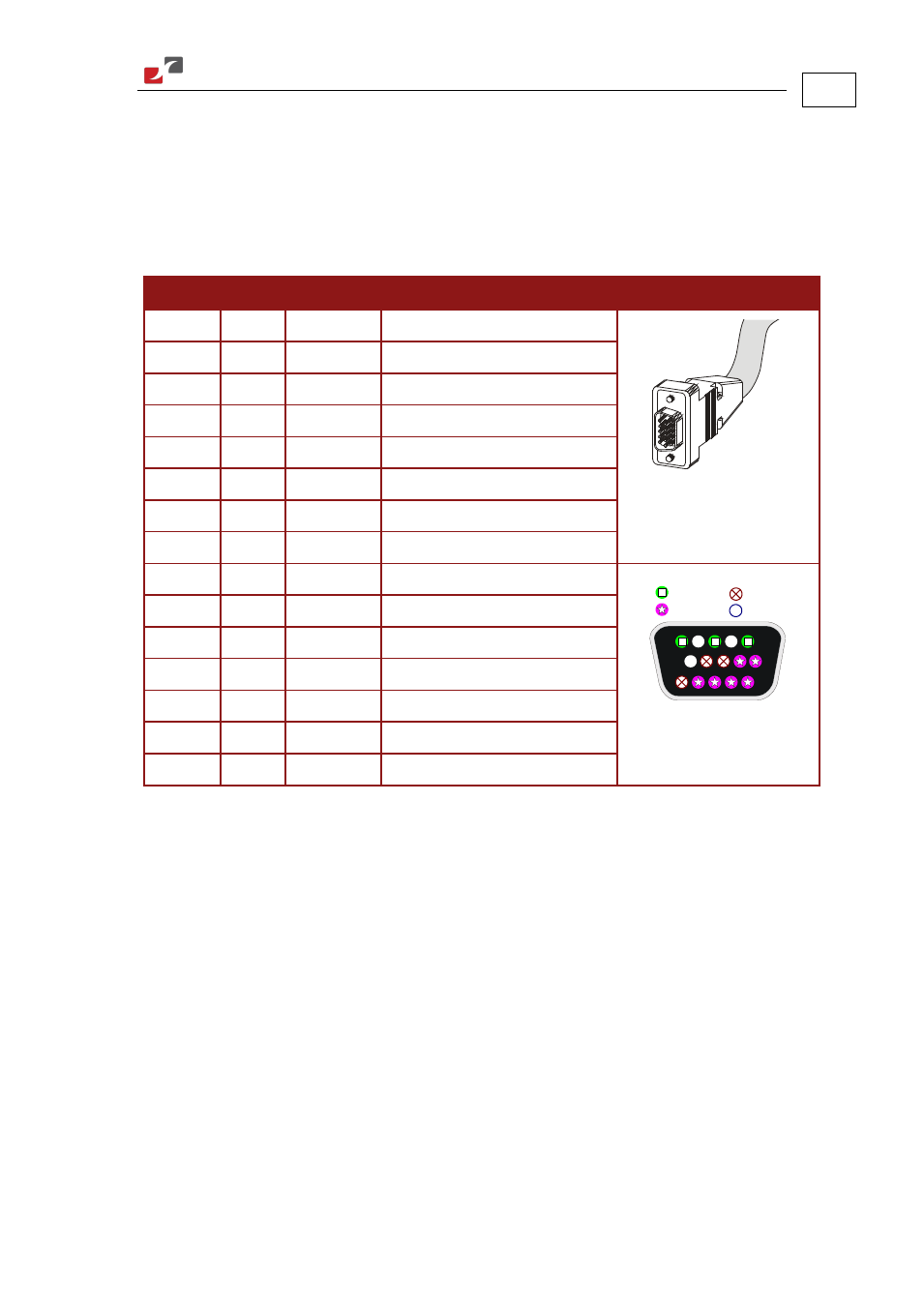
Below are the signals on the Auxiliary Feedback ports when set up to run as a single-ended
auxiliary input:
Port
Pin
Signal
Function
Pin Positions
B1
1
CHA
Auxiliary channel A high input
15-Pin High Density D-Sub
Plug
2
NC
Do not connect this pin
B1
3
CHB
Auxiliary channel B high input
4
NC
Do not connect this pin
B1
5
INDEX
Auxiliary Index high input
B2
6
CHAO
Channel A output
B2
7
CHAO-
Channel A complement output
PWR
8
+5V
Encoder supply voltage
PWR
9
SUPRET
Encoder supply voltage return
5
15
10
1
11
6
Port B1
Port B2
Power
N.C.
15-Pin High Density D-Sub
Socket
10
NC
Do not connect this pin
B2
11
CHBO
Channel B output
B2
12
CHBO-
Channel B complement output
B2
13
INDEXO
Index output
B2
14
INDEXO-
Index complement output
PWR
15
SUPRET
Supply return
Table 10: Single-Ended Auxiliary Encoder Option on FEEDBACK B - Pin Assignments
FEEDBACK B on the “top” of the Cello has a 15-pin high density D-Sub socket. Connect the
Auxiliary Feedback cable from the feedback device to FEEDBACK B using a 15-pin, high density
D-Sub plug with a metal housing. When assembling the Auxiliary Feedback cable, follow the
instructions in Section 3.4.4 (Feedback and Control Cable Assemblies).