3 system architecture, 4 how to use this guide, System architecture – ElmoMC SimplIQ Digital Servo Drives-Cello Installation Guide User Manual
Page 13: How to use this guide
Cello Installation Guide
Introduction
MAN-CELIG (Ver. 1.602)
13
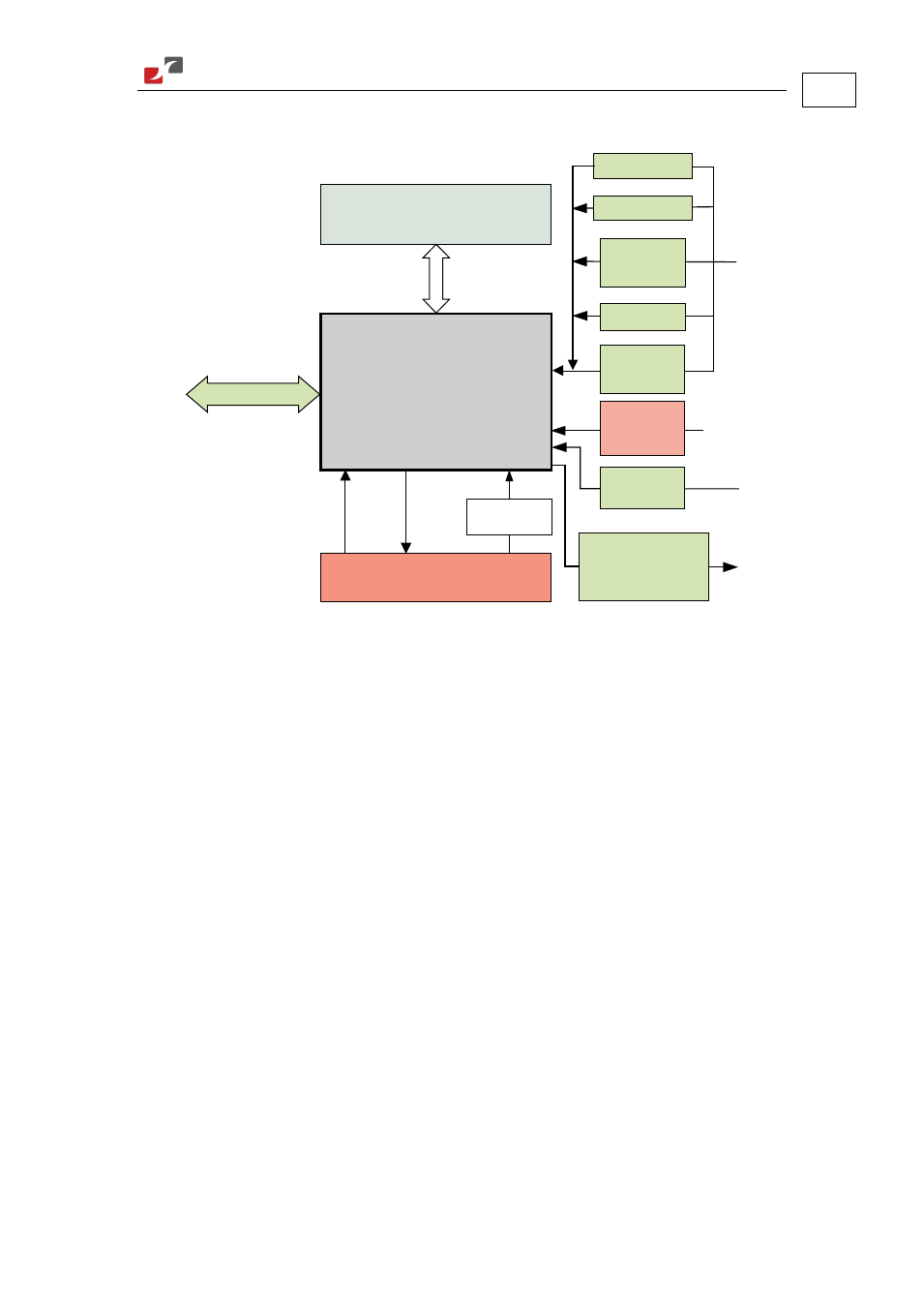
2.3 System Architecture
Auxiliary
Power
Supply
PWM
Controller
Power Stage
Protection
Current
Feedback
Incremental
Encoder
24 VDC
I/Os
Incremental Encoder
Buffered Output
or
Emulated Output
Resolver
Analog
Encoder
Auxiliary
Encoder
or
or
Potentiometer
Tachometer
or
or
Communication
RS 232 and CANopen
Figure 1: Cello System Block Diagram
2.4 How to Use this Guide
In order to install and operate your Elmo Cello servo drive, you will use this manual in
conjunction with a set of Elmo documentation. Installation is your first step; after carefully
reading the safety instructions in the first chapter, the following chapters provide you with
installation instructions as follows:
Chapter 3, Installation
, provides step-by-step instructions for unpacking,
mounting, connecting and powering up the Cello.
Chapter 4, Technical Specifications
, lists all the drive ratings and specifications.
Upon completing the instructions in this guide, your Cello servo drive should be successfully
mounted and installed. From this stage, you need to consult higher-level Elmo documentation
in order to set up and fine-tune the system for optimal operation. The following figure
describes the accompanying documentation that you will require.