4 auxiliary power, Auxiliary power – ElmoMC Gold Line Digital Servo Drives-Gold DC Trombone User Manual
Page 36
Gold DC Trombone Installation Guide
MAN-G-DCTROIG-EC (Ver. 1.900)
||Auxiliary Power
36
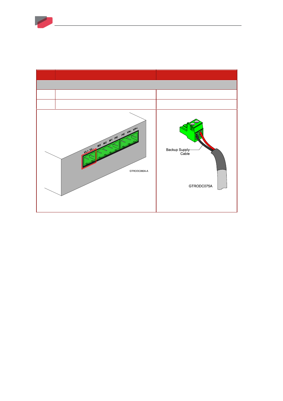
6.4 Auxiliary Power
Optional Backup Supply in A, H, S, or T option drives.
See Chapter 8 in the in the MAN-G-Panel Mounted Drives Hardware manual for full details.
Pin
Function
Cable
A, H, S, or T option type
VL+
+24 V Auxiliary Supply Input Positive
DC Power
VL-
24 V RET Auxiliary Supply Input Return
DC Power
2-Pin Pluggable 5.08 mm Phoenix High Current
2-Pin Phoenix Plug-in Connector
Table 4: Auxiliary Power Connector
In drives that have a 0 or 1 Option (only for 400 V model) in the catalog number, a smart control-
supply algorithm enables the Gold DC Trombone to operate with the main power supply only, with
no need for an auxiliary supply voltage to supply the drive’s logic section.
Note that in such a model there is no backup ability at all.
If backup functionality is required to store control parameters in the event of a mains power
outage, then an A, H, S, or T options Gold DC Trombone should be used, with an external 24 VDC
isolated supply connected to it.
Note that the A, H, S, or T options Gold DC Trombone always requires an external 24 VDC power
supply, regardless of whether or not backup functionality is required.
Connect the auxiliary 24 VDC power supply as described below.
To connect the 24 VDC backup supply:
1.
Use a 24 AWG twisted pair shielded cable. The shield should have copper braid.
2.
The source of the 24VDC backup supply must be isolated with an isolation transformer.
3.
For safety and EMI reasons, connect the return of the 24VDC backup supply to the closest
ground (PE).
4.
Connect the cable shield to the closest ground (PE) near the power source.
5.
Before applying power, first verify that the polarity of the connection is correct.