Det-Tronics UD10 FlexVu Universal Display SAFETY MANUAL User Manual
Page 4
2.1
95-8668
4
NOTE
The actual 4-20 mA output can be read on the
UD10 display by navigating to:
Display Status > Debug Menu > Output Readback.
“Output Readback” is the actual 4-20 mA output
as read by the UD10.
Configuration protection
Upon completion of installation and commissioning, it is
required that the user password-protect the UD10 safety
related parameters that are accessible via the faceplate
display, HART, MODBUS, or Foundation Fieldbus in
order to prevent accidental or deliberate change of
configuration data during normal operation. To password
protect the UD10, the user must set the write-protect
function to “on” and enter an 8 character password.
The user will be required to disable write protect prior to
any future configuration changes, and must re-enable
write protect upon completion of these changes.
OpERATION, MAINTENANCE, INSpECTION AND
pROOF TESTING
All normal installation, start-up, and field calibration
recommendations as documented in the UD10
instruction manual are applicable to the Safety Certified
UD10 Universal Display.
Safety-Certified UD10 Universal Displays require
additional Proof testing to be performed in all cases.
Personnel performing Proof Test procedures shall be
competent to perform the task. All proof test results
must be recorded and analyzed. Any corrective actions
taken must be documented in the event that an error is
found in the safety functionality. The Proof tests must be
performed at a frequency as shown in Table 1.
WARNING
Failure to perform the specified testing and
inspection may lower or void the SIL rating for the
product or system.
vISUAL FIELD INSpECTION pROOF TEST
Tools Required: None
Visual inspection of Safety-Certified UD10 and
connected devices shall be conducted as needed
to confirm that no external blockage of path into the
sensing chamber/area exists, eg. debris, trash, snow,
mud, external equipment, etc. Corrective action shall
include removal of such impediments should they
exist. All devices monitored by the UD10 must be
inspected to ensure that they are capable of providing
expected performance and protection.
Completion of Visual Field Inspection Proof test must
be recorded and documented in the SIS logbook.
RESpONSE pROOF TEST
Tools Required: Compressed Calibration Gas Kit
provided by Det-Tronics, or other
device stimulation method
The Response Proof Test must be performed while the
UD10 and attached device are in NORMAL operation
and requires application of sufficient stimulation to put
the device into alarm state. The user must then inspect
the signal output level to ensure that the signal output
is accurately indicative of the applied condition.
WARNING
Any external alarm equipment, systems or
signaling devices that could be automatically
initiated by performing this test must be disabled
or bypassed before performing this test!
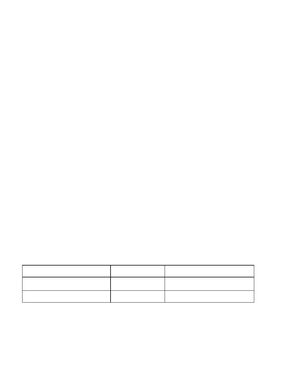
UD10 proof Test Name
Commissioning
Frequency
Visual Field Inspection Proof Test
Yes
As needed, depending on level and type of
contaminants present
Response Proof Test
Yes
10 years
Table 1—Frequency for Performing Proof Tests