Det-Tronics UD10 FlexVu Universal Display SAFETY MANUAL User Manual
Page 3
2.1
95-8668
3
COMMON MISUSE SCENARIOS
Refer to the Installation and Troubleshooting sections
of the instruction manual for detailed information on
avoidance and resolution of common misuse scenarios.
Applications to avoid include the following:
- Locations where impact or other excessive
mechanical stress is likely.
- Locations where the UD10 display is not easily
viewable or accessible.
- Mounting the UD10 without properly sealing ALL
conduit entries.
START-Up AND COMMISSIONING
NOTE
All safety functions of the UD10 are active within
150 seconds of power-up without any user action
required.
Commissioning personnel
The Safety Certified UD10 Universal Display can be
commissioned by any qualified person with knowledge
of the detection instruments and configuration devices
being used. Refer to the Start-Up and Calibration
sections provided in the UD10 instruction manual.
Configuration
The UD10 faceplate display or a HART handheld device
can be used to monitor internal status or to modify the
factory settings. Refer to the UD10 instruction manual
for guidance on using the UD10 LCD display, HART,
MODBUS, or Foundation Fieldbus communication.
Specifics on HART or UD10 display communication can
be found in the appropriate Appendix of the instruction
manual. The proper Appendix is determined by the
sensor being used with the UD10.
NOTE
Prior to device configuration (setting alarm
thresholds, latch/non-latch function, etc.) all
alarm outputs must be bypassed. The device is
not safety certified during configuration change
activities.
NOTE
All configuration changes to the UD10 must be
verified by the user via a proof test, power cycle
and re-check of settings, or other appropriate
method.
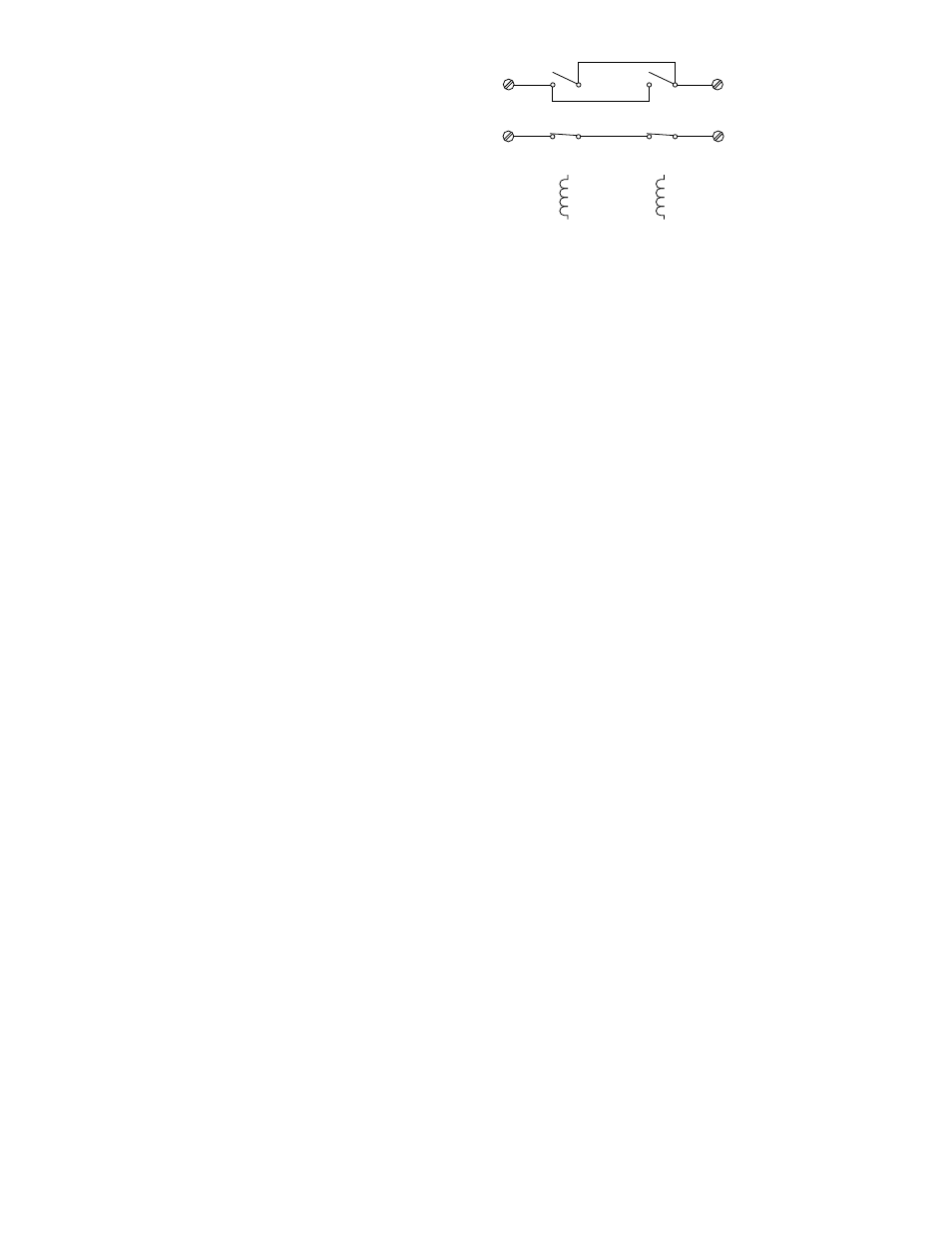
Relay Configuration Requirements
Only the UD10’s Alarm and Fault relay outputs may
be used as part of a Safety Certified system. The
High Alarm and Auxiliary relays must be configured
identically to operate as a pair. The end user must
monitor the High Alarm and Auxiliary relays as a pair
using either the NO contacts wired in parallel or the NC
contacts wired in series. See Figure 1. The end user
must provide transient protection and current limiting
on the output contacts of the relays. The maximum
relay contact output must be limited to 2 amperes at 30
Vdc. The load must be a resistive load. The user must
protect against transients by using standard protection
methods such as proper grounding of shielded wire
and separation of relay load wires from other lines
carrying rapidly switched high current (e.g. large motor
power supply lines).
If the 0-20 mA analog output of the UD10 is not being
monitored for fault conditions, the status of the Fault
relay must be monitored and appropriate action taken if
a fault signal is received.
4-20 mA Configuration Requirements
The UD10 must be configured to use the 4-20 mA
output loop diagnostic. This diagnostic ensures that
the 4-20 mA output is being driven to the correct level.
To enable this function, navigate the HART menu as
follows:
Main Menu > Display Setup > OP Feedback Flt.
Select ON.
After enabling the output loop diagnostic function,
perform an output loop calibration. Refer to the “UD10
Output Trim” section in the UD10 Instruction Manual
(number 95-8661) for detailed instructions.
OPEN = NORMAL OPERATION
CLOSED = ALARM
CLOSED = NORMAL OPERATION
OPEN = ALARM
HIGH ALARM
(DE-ENERGIZED)
AUXILIARY
(DE-ENERGIZED)
NO
NO
NC
NC
A2588
Figure 1—High Alarm and Auxiliary Relays
Configured as a De-Energized Pair