Det-Tronics UD10 FlexVu Universal Display SAFETY MANUAL User Manual
Page 2
2.1
95-8668
2
DESIGN
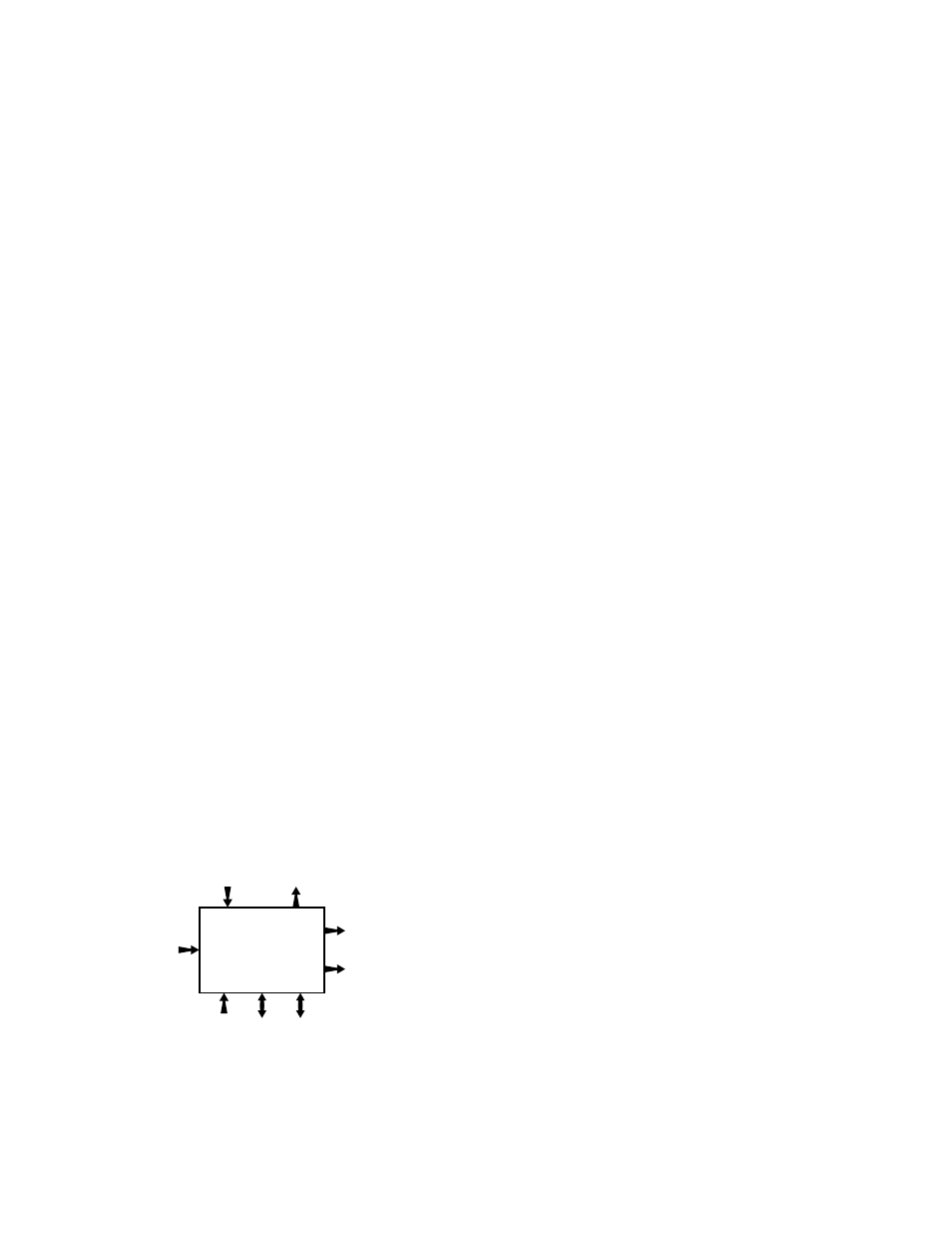
The Model UD10 Universal Display is a stand alone
device that performs all the functions of a gas controller
and is classified as Type B smart device according to
IEC61508. It provides an isolated 4-wire 4-20 mA output
that is representative of the received input 4-20 mA
level. The UD10 contains extensive self-diagnostics
and is programmed to send the current output to a
specified failure state upon internal detection of a
failure (see UD10 instruction manual for details). Alarm
and Fault relay contact outputs are provided in addition
to the analog signal output, and can be programmed
in the field by the user. The relay output and analog
output are not to be used in combination for the safety
function.
Safety-Certification of the UD10 Universal Display
includes:
• the 4-20 mA input and output
• the High Alarm, Auxiliary, and Fault relay outputs
Safety Certification of the UD10 Universal Display
includes the following non-interfering outputs:
- UD10 display and magnetic switches
- HART communication
- Modbus communication
- Foundation Fieldbus communication.
The HART communication protocol is non-interfering
and is to be used for diagnostics within the SIL 2
safety loop in the Safety operation mode. Diagnostics
are defined as read only information. Local HART
communication with the UD10 Universal Display using
a handheld HART field communicator, or AMS program
connected to the 4-20 mA output, is acceptable. Proper
analog signal loop resistance must be installed as
documented in the instruction manual to enable local
HART communication.
vALID INpUT RANGE
UD10 fault annunciation is provided on the 4-20 mA
signal output loop by signaling to a specific mA current
output level. The receiving device must be programmed
to indicate a fault condition when current levels reach
undercurrent of 3.6 mA or less.
NOTE
The UD10 analog signal and relay outputs are not
safety-rated during detector warm-up, calibration
mode, or during signal output loop testing.
Alternative means should be used at the job site
to ensure facility safety during these activities.
DIAGNOSTIC RESpONSE TIME
The UD10 Universal Display will perform all critical
diagnostic functions within 58 minutes, worst case
diagnostic detection time.
CERTIFICATION
The UD10 Safety-Certified version is certified by exida
®
to IEC61508 for single input use in low demand, SIL 2
Safety Instrumented Systems.
SAFETY-CERTIFIED pRODUCT IDENTIFICATION
Safety Certification of all UD10 models meeting SIL 2
safety standards is clearly identified on the product label.
INSTALLATION
NOTE
For complete information regarding performance,
installation, operation, maintenance and
specifications of Model UD10, refer to instruction
manual 95-8661.
No special or additional detector installation
requirements exist above and beyond the standard
installation practices documented in the Model UD10
instruction manual.
The operating temperature range for the Safety
Certified UD10 is –55°C to +75°C for the analog output
and –45°C to +75°C for the relay outputs. Other
environmental operating specifications are applicable
as published in the general specifications section in the
Model UD10 instruction manual.
The UD10 operating power distribution system should
be designed and installed so the terminal voltage does
not drop below 18 Vdc when measured at any specific
location. The maximum current limit per device must
be less than 2 amperes. The external system providing
power to the UD10 must have over-voltage protection
that ensures supply voltage does not exceed 30 Vdc.
UD10
Universal
Display
4-20 mA Current Loop
with HART
(HART Master)
4-20 mA Current Loop
(HART Slave)
Relay Outputs
(Fault, High Alarm,
Auxiliary)
24 VDC
Visual Outputs
(Output Meter,
Alarm & Menu)
Ma
gnetic S
witc
hes
MODB
US /
Foundation F
ieldb
us
HAR
T
(via 4-20 mA Output)
Power
Visual
Input
Outputs
Configuration & Maintenance