Calibration – Det-Tronics UD20 FlexVu Explosion-Proof Universal Display Unit User Manual
Page 8
3.1
95-8620
6
cAlibrAtion
The calibration process is automatic, with the exception
of gas delivery. LEDs on the GT3000 and messages on
the UD20 faceplate guide the operator when to apply
and remove the calibration gas. See Table 1.
NOTE
The UD20 allows the operator to adjust the
calibration gas concentration within the range of
30 to 90% full scale. The default value for all gas
sensors except oxygen is 50% full scale. Oxygen
sensors use a default value of 20.9%.
gENERAl CAlIbRATION INfORmATION
All GT3000 Gas Detectors require a two-point
calibration — zero and span.
The calibration process can be initiated using the
magnetic switch on the GT3000 or using the magnetic
switches on the UD20 faceplate. All sensors, including
oxygen, should be in clean air (20.9% oxygen) when
the calibration sequence is initiated.
Once calibration is initiated, the process proceeds
automatically. The yellow LED on the GT3000 and
the digital display on the UD20 are used to inform the
operator of the progress of the calibration procedure,
and also signal when to apply and when to remove the
calibration gas.
The calibration can be aborted after zero calibration
by activating the magnetic switch on the GT3000 or
navigating the UD20 menu.
If the calibration sequence is aborted or not completed
successfully, the detector reverts back to the previous
calibration values and signals a calibration fault. If
a successful calibration cannot be performed, the
calibration fault can be cleared by activating the
magnetic switch on the GT3000 for one second.
For help assessing when a fault has occurred see Table
2.
The calibration process can fail for the following causes:
• Zero is out of range
• Span is out of range
• Time-Out.
The time and date of calibration events are logged
in the GT3000’s non-volatile memory along with the
calibration outcome. Possible calibration scenarios
include the following:
• Successful Calibration
• Aborted Calibration
• Failed Calibration
NOTE
The calibration procedure must be completed
within a ten minute period. If the calibration is not
completed, a calibration fault will be generated
and the previous calibration data will be used.
NOTE
To ensure reliable protection, it is important to
check and calibrate the detection system on a
regularly scheduled basis. The frequency of these
checks is determined by the requirements of the
particular installation – typically 30, 60, or 90 day
intervals, depending on the ambient conditions.
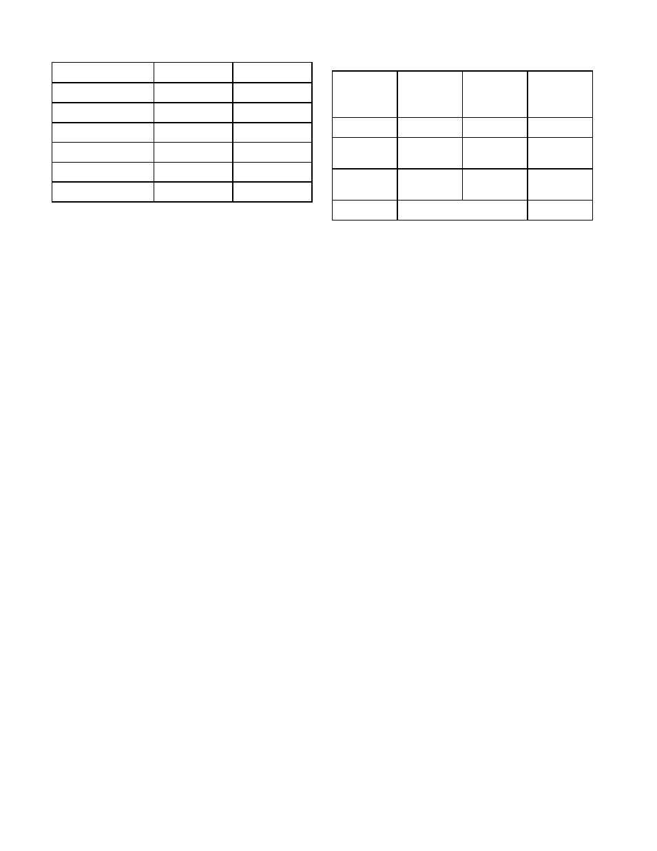
Device Status
green lED
yellow lED
Normal
Steady On
Off
Waiting for Zero
Off
Steady On
Waiting for Gas
Off
Blinking
Waiting for Span
Off
Blinking
Remove Cal Gas
Off
Off
Normal
Steady On
Off
Table 1— GT3000 LEDs During Calibration
Table 2— GT3000 LEDs and 4-20 mA Output
During Various Status Conditions
function
green
lED
yellow
lED
Analog
4-20 mA
Signal
Warm-up
Off
Steady On
3.5
Normal
Operation
Steady On
Off
4-20
Fault
Condition
Off
Steady On
3.5
Calibration
See Table 1
3.8