Wiring – Det-Tronics UD20 FlexVu Explosion-Proof Universal Display Unit User Manual
Page 6
3.1
95-8620
4
DEvICE mOUNTINg ORIENTATION
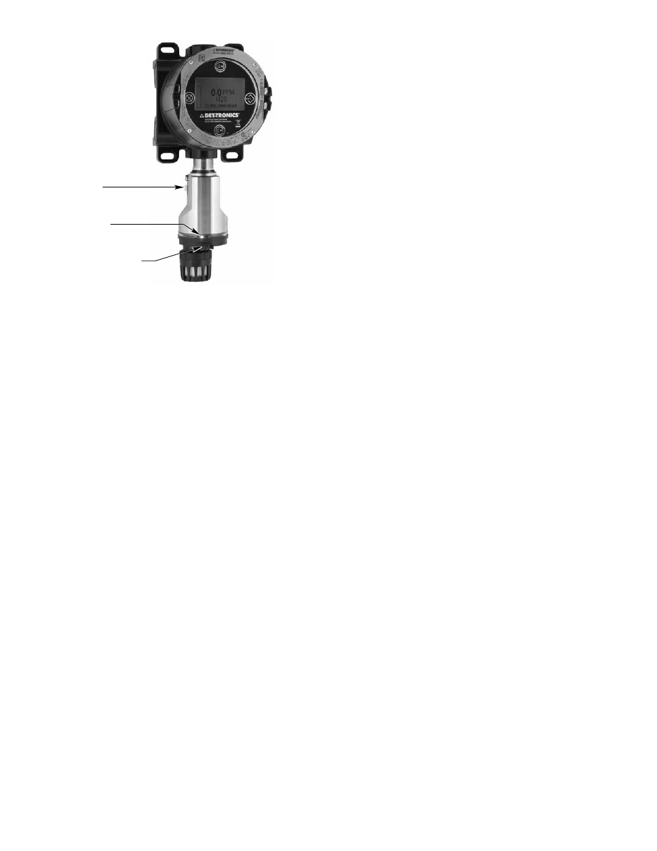
The gas detector must be mounted in a vertical position
only, with the sensor pointing down. See Figure 2.
Important
The GT3000 must be oriented with the LEDs
facing forward so they are easily visible to
personnel within the area. To ensure correct
orientation (the LEDs are not visible when power
is off), position the GND lug on the left hand side
and the calibration notch to the front. Note that the
LEDs are located directly above the calibration
notch.
SENSOR SEpARATION
Det-Tronics sensor termination boxes (Model STBs)
enable the installation of the GT3000 separately from
the UD20 Universal Display Unit. Two-conductor
shielded cable is required to prevent possible nuisance
EMI/RFI.
The maximum cable length between the termination
box and the UD20 is 2000 ft.
WirinG
pOwER SUpply REqUIREmENTS
Calculate the total gas detection system power
consumption rate in watts from cold start-up. Select a
power supply with adequate capability for the calculated
load. Ensure that the selected power supply provides
regulated and filtered 24 Vdc output power for the
entire system. If a back-up power system is required,
a float-type battery charging system is recommended.
If an existing source of 24 Vdc power is being utilized,
verify that system requirements are met.
NOTE
The UD20 and GT3000 communicate using
HART protocol, which requires a power supply
with low noise levels for proper operation. (For
detailed information regarding power supply
specifications, refer to the HART Communication
Foundation’s document “FSK Physical Layer
Specification” HCF_SPEC-54.)
wIRINg CAblE REqUIREmENTS
Always use proper cabling type and diameter for input
power as well as output signal wiring. 22 to 14 AWG
shielded stranded copper wire is recommended.
Always install a properly sized, master power fuse or
breaker on the system power circuit.
NOTE
The use of shielded cable in conduit or shielded
armored cable is required. In applications where
the wiring is installed in conduit, dedicated
conduit is recommended. Avoid low frequency,
high voltage, and non-signaling conductors to
prevent nuisance EMI problems.
CaUtIon
The use of proper conduit installation techniques,
breathers, glands, and seals is required to prevent
water ingress and/or maintain the explosion-proof
rating.
wIRINg pROCEDURE
Refer to Figures 3 and 4 for wiring illustrations.
GREEN LED
CALIBRATION NOTCH
B2436
GND LUG
Figure 2—Correct Mounting Orientation