Despatch Protocol Plus Modbus Communications User Manual
Page 47
Chromalox Instruments and Controls
A-51643 Rev. 6 10/06/03
41
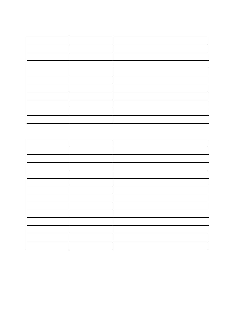
Query
Field Name
RTU Example Data
Description
Header
> 3.5 idle characters
Start characters
Slave Address
$06
Slave number 6
Function
$03
Read multiple registers
Starting Address Hi
$00
Start reading at holding register 108
Starting Address Lo
$6B
No. of Registers Hi
$00
Read 3 successive holding registers
No. of Registers Lo
$03
CRC Lo
$75
CRC = $A075
CRC Hi
$A0
Trailer
> 3.5 idle characters
End characters
Response
Field Name
RTU Example Data
Description
Header
> 3.5 idle characters
Start characters
Slave Address
$06
Slave number 6
Function
$03
Read multiple registers
Byte Count
$06
Number of data bytes to follow
Data Hi
$02
Contents of holding register 108
Data Lo
$2B
Data Hi
$00
Contents of holding register 109
Data Lo
$00
Data Hi
$00
Contents of holding register 110
Data Lo
$62
CRC Lo
$88
CRC = $8862
CRC Hi
$49
Trailer
> 3.5 idle characters
End characters
6.7.1
The Byte Count Field
When constructing responses in buffers, use a Byte Count value that equals the count of 8-bit bytes in
your message data. The value is exclusive of all other field contents, including the Byte Count field.