Despatch Protocol Plus Modbus Communications User Manual
Page 31
Chromalox Instruments and Controls
A-51643 Rev. 6 10/06/03
25
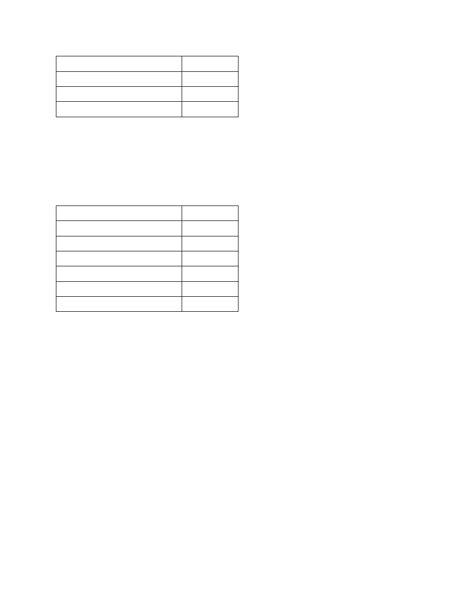
Starting address lo
$09
Number of registers hi
$00
Number of registers lo
$01
CRC
$----
Response
The register data in the response are packed as two bytes per register (one word). For each register, the
first byte contains the high order bits and the second contains the low order bits.
Example response:
Field Name
Data
Slave address
$11
Function
$04
Byte count
$02
Data (register 10 hi)
$00
Data (register 10 lo)
$23
CRC
$----
5.2.5
[06] Write Single Register
Class 1 command. Writes a value into a single holding register. When broadcast, the value is written to
the same register reference in all slaves on the network. Use of broadcast with this command should be
used with caution as the register addressed may differ in function on each slave device in the network.
Note: The written value will remain valid until the controller‘s next write to the register through its
keypad or internal logic.
Query
The query message specifies the register reference to be written. Registers are addressed starting at zero.
The requested value is specified in the query data field in two bytes (one word). The first byte represents
the high order bits and the second byte represents the low order bits.
Example: Request to preset register 2 to the value 3 in slave device 14.