Despatch Protocol Plus Modbus Communications User Manual
Page 33
Chromalox Instruments and Controls
A-51643 Rev. 6 10/06/03
27
high order bits and the second byte the low order bits. Next, the actual number of data bytes is
transmitted (one byte). The requested values are specified in the query data field in two bytes (one word)
per register. The first byte represents the high order bits and the second byte represents the low order bits
of the register value.
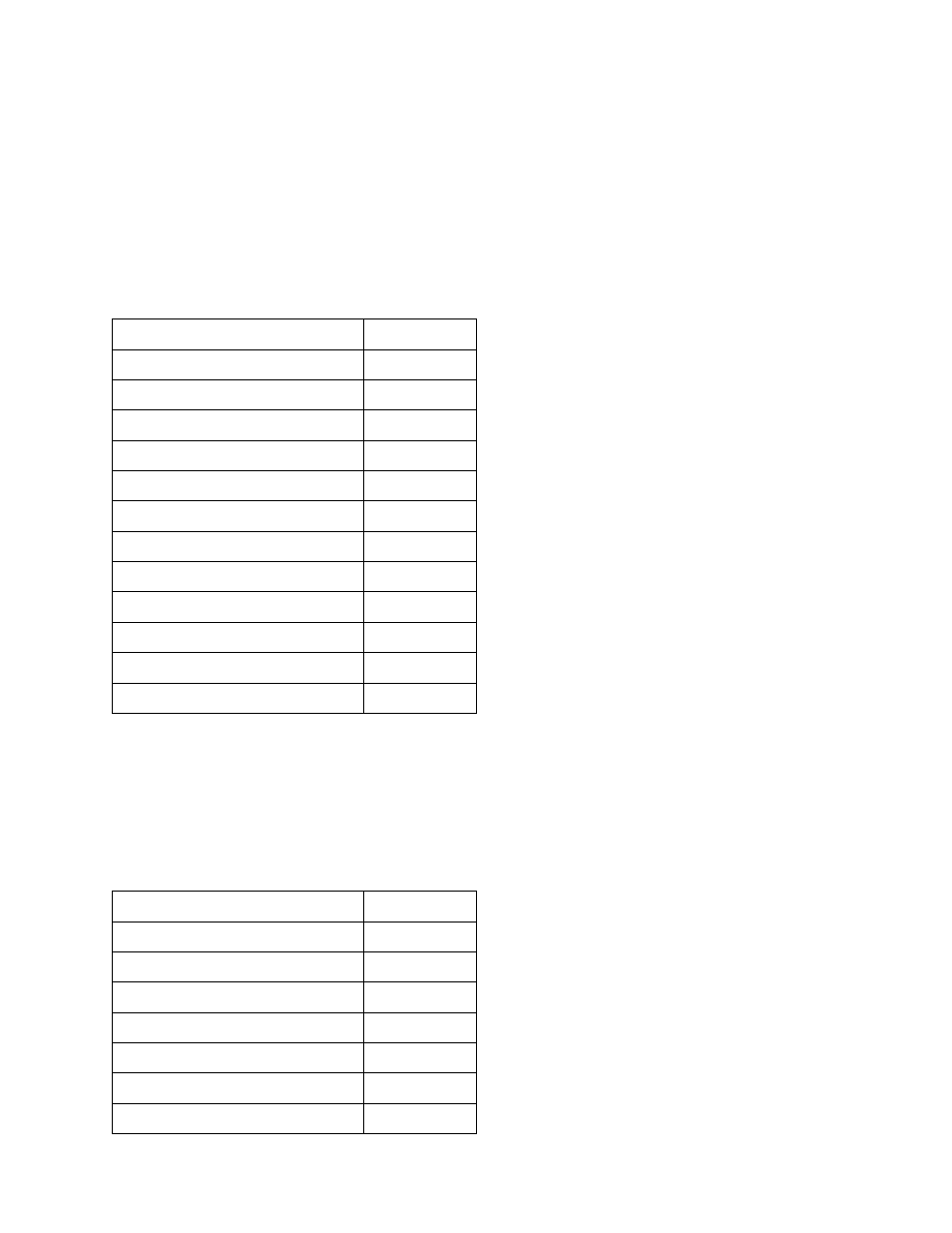
Example: Request to preset two registers starting at register 5 to the values of 10 and 258 respectively in
slave device 14.
Field Name
Data
Slave address
$0E
Function
$10
Starting register address hi
$00
Starting register address lo
$04
Number of registers hi
$00
Number of registers lo
$02
Byte count
$04
Data hi (register 5)
$00
Data lo (register 5)
$0A
Data hi (register 6)
$01
Data lo (register 6)
$02
CRC
$----
Response
The normal response returns the slave address, function code, starting address, and quantity of registers
written.
Example response:
Field Name
Data
Slave address
$0E
Function
$10
Starting register address hi
$00
Starting register address lo
$04
Number of registers hi
$00
Number of registers lo
$02
CRC
$----