Comelit MT VIP SYSTEM User Manual
Page 6
6
1
2
3
4
The Ethernet Switch module art. 1440 performs two main functions:
• Directing data ViP system data packages.
• Provide a power supply for the extensions connected to it and to any switch/repeaters connected in cascade.
Description
1.
Port status indicator LED.
Lit steadily: port in standby.
Flashing: data passing through the port.
Off: port not connected.
2.
10 Mb extension Ethernet port.
Used for the connection of distributors, such as repeaters, switches, internal units etc...
3.
External power supply terminals.
Connection of power supply unit art. 1441 or art. 1441A.
4.
100 Mb riser Ethernet ports.
Used for the connection of distributors, such as repeaters, switches, internal units etc...
Switch art. 1440
Technical characteristics
Absorption
Min. 0.7 W Max. 2.6 W
Power supply
36/57 Vdc 3A Max.
Temperature thresholds
-30 / +55°C
Dimensions
4 DIN modules / H: 6.2 cm W: 7.2 cm D: 9 cm
1
2
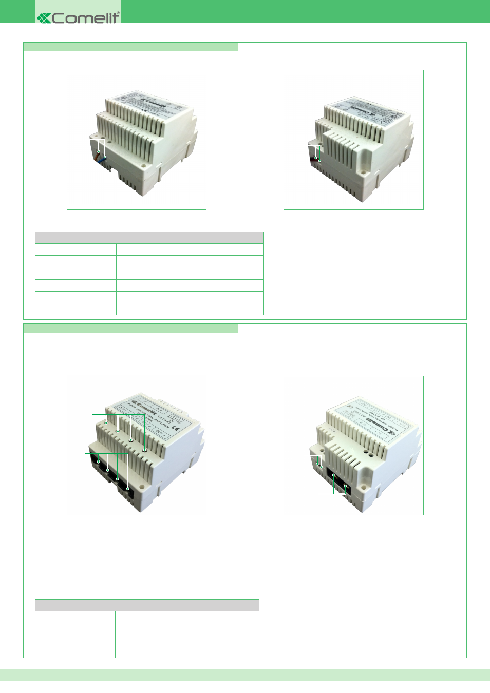
Power supply unit art. 1395
Power supply unit art. 1395, for powering external units.
1.
230 V ~: Alternating 230 Vac network terminals.
2.
0 12~: Power supply output terminals.
Technical characteristics
Input voltage
207 - 257 V AC (3 A)
Output voltage
13.1 - 15.9 V DC (1.8 A)
Power
60 W
Frequency
50 Hz
Temperature thresholds
-20 / +40°C
Dimensions
4 DIN modules / H: 9 cm W: 7.15 cm D: 6.2 cm
N.B. For correct operation of the system protecting
art. 1440, the riser must be connected with input on
port IN1 and output on port IN2.