Prepare site • prepare burner • mount burner, Model g3b gas burner — instruction manual, 6prepare the appliance – Carlin G3B User Manual
Page 6: Input minimum chamber dimensions
Model G3B Gas burner — Instruction manual
Carlin part number MNG3B Gas Rev. 03/17/09
6
Prepare the appliance
Burner input: Install a gas burner sized for the normal input
rating of the appliance. Do not install a burner with a higher
fi ring rate than the appliance rating. Do not install a burner
with a fi ring rate more than 10% lower than the appliance
rating. The appliance and vent system could be damaged
due to condensation.
Seal the appliance: Seal all fl ue-gas containing joints. Seal
all connections to the vent piping or breeching.
Clean and check the appliance: Clean the appliance
thoroughly. Test all electrical components and verify the
relief valve works (boilers only).
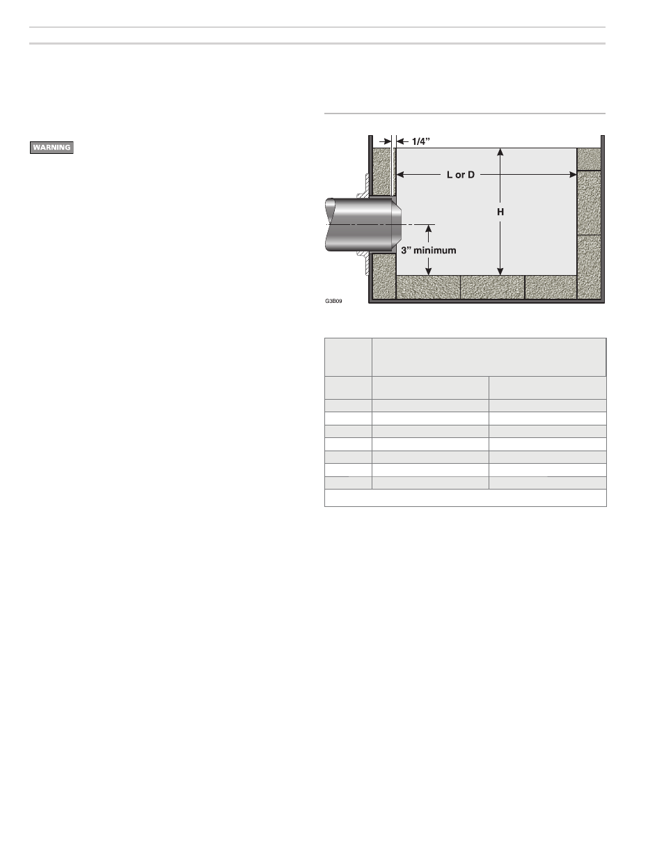
Verify combustion chamber dimensions comply with the
minimum dimensions shown in Figure 3. Install or replace
combustion chamber liner if required by the appliance
manufacturer. The burner air tube must not extend into the
combustion chamber. The end of the burner air tube must be
within ¼” of the inside face of the combustion chamber. If the
space around the burner air tube is more than ¼”, wrap the
burner air tube with minimum 2300-°F-rated ceramic fi ber
blanket to seal off the gap. Notice that the fl ameholder may
extend slightly into chamber as shown in Figure 3.
Repair or replace damaged appliance components. Inspect
the appliance thoroughly. Follow appliance manufacturer’s
guidelines for repair or replacement of any component found
defective.
When cleaning the appliance or working with ceramic fi ber
refractories or fi berglass insulation, see WARNING on page
7.
Failure to comply with the above could result in severe
personal injury, death or substantial property damage.
1. Prepare site • prepare burner • mount burner
(continued)
Input
Minimum chamber dimensions,
Inches
(Note 1)
(Using 2300ûF or higher refractories)
Btuh
Square
L x W x H
Vertical cylinder
Diameter x H
60,000 7 x 7 x 9
8 x 9
70,000 7½ x 7½ x 9
8½ x 9
100,000 8 x 8 x 9
9 x 9
120,000 9 x 9 x 9
10 x 9
140,000 10 x 10 x 9
11 x 9
160,000 11 x 11 x 9
12 x 9
180,000 12 x 12 x 9
13 x 9
Note 1: Rectangular chambers of similar fl oor area are equally acceptable, but the L/W ratio should not
exceed 2 and the width should be at least 5 inches.
Figure 3 Minimum combustion chamber dimensions