G3b gas burner at-a-glance, Model g3b gas burner — instruction manual – Carlin G3B User Manual
Page 3
Model G3B Gas burner — Instruction manual
Carlin part number MNG3B Gas Rev. 03/17/09
3
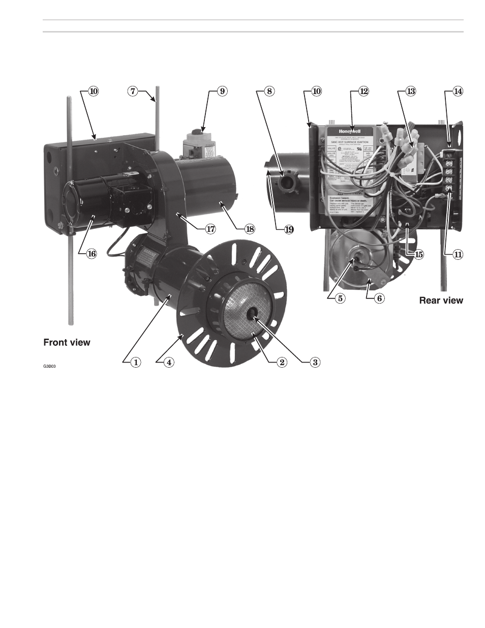
G3B Gas burner at-a-glance
1 Air tube, with powder coat paint fi nish
2 Flameholder
3 Hot surface ignitor
4 Adjustable
fl
ange
5 Rear ignitor assembly with terminal boots
6 Ignition tube assembly mounting plate
7 Pedestal
legs
8 Burner gas inlet connection (see page 8)
9 Combination gas valve (with integral gas pressure regulation — set
for 3½” w.c. outlet pressure)
10 Control panel
11 Terminal strip
12 Primary control (Honeywell Model S89C primary control, for use with
fl ame rectifi cation)
13 Control transformer, 120
VAC
/ 24
VAC
, 40
VA
14 Gas valve on indicator light
15 Motor relay
16 High-effi ciency motor
17 Blower housing (cast aluminum), with powder coat paint fi nish
18 Air inlet tube assembly
19 Air throttle indicator — Only a single adjustment required for setting
combustion air; see page 8 for starting setting based on appliance
model and input)