Circuit diagram – Carbolite HTF 18 User Manual
Page 16
MF47-3.05
16
7.0 C
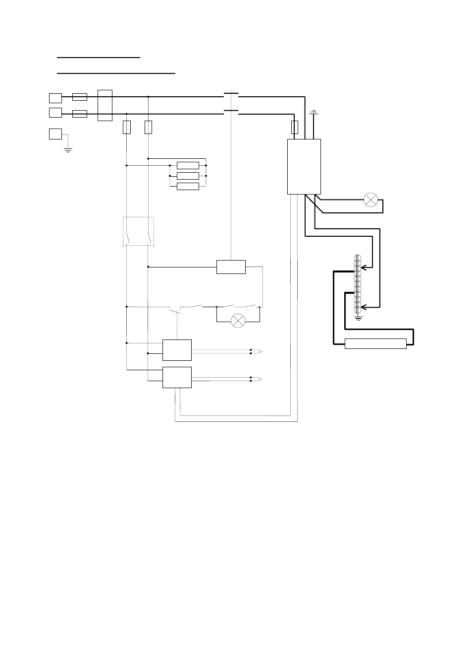
IRCUIT
D
IAGRAM
7.1 Single Phase 208V, 220-240V
thermal cutouts:
case temperature sensor
transformer temperature sensor
TC
temperature controller
OTC overtemperature controller
F1
Supply fuses (present if supply cable fitted)
F2
Auxiliary circuit fuses (2A)
F4
Thyristor protection fuse (Ferraz Protistor)
BU
Blue
R
Red
P
Pink
G
Grey
GR/Y Green & Yellow
Coil
N
Elements
Contactor
BU
R
Thyr
-
istor
BU
R
OTC
P
G
TC
Control
thermocouple
O/temp
thermocouple
Door
Switch
Element
Transformer
Heat
Light
Case Cooling Fans
F2
F1
GR/Y
PE
L
EMC
Filter
F4
Thermal
Cutouts
Fault Light
Instrument Switch
This manual is related to the following products: