Repairs, replacements & adjustments, On 5.3). t, Ons 5.4 – Carbolite HTF 18 User Manual
Page 10: On 5.4
MF47-3.05
10
5.0 R
EPAIRS
,
R
EPLACEMENTS
&
A
DJUSTMENTS
5.1 Safety Warning – Disconnection from Supply
Always ensure that the furnace is disconnected from the electrical supply before
repair work is carried out. Note: the Instrument switch on the front panel does not
isolate the furnace from the supply.
5.2 Safety Warning - Refractory Fibrous Insulation
Insulation made from High Temperature Insulation Wool
Refractory Ceramic Fibre, (better described as Alumino Silicate Wool)
(ASW)
This product contains alumino silicate wool products in its thermal insulation. These materials
may be in the form of blanket or felt, formed board or shapes, mineral wool slab or loose fill wool.
Whilst there is no evidence of any long term health hazards, we strongly recommend that safety
precautions are taken whenever the materials are handled.
Exposure to fibrous dust may cause respiratory disease.
When handling the material always use an approved respiratory protection equipment
(RPE-i.e. FFP3), eye protection, gloves and long sleeved clothing.
Avoid breaking up waste material. Dispose of waste in sealed containers.
After handling rinse exposed skin with water before washing gently with soap (not
detergent). Wash work clothing separately.
Before commencing any major repairs we recommend reference to the European Association
representing the High Temperature Insulation Wool industry
We can provide further information on request. Alternatively our service division can quote for
any repairs to be carried out at your premises or ours.
5.3 Side Panel Removal
Except where explicitly stated, always disconnect the electrical supply before removing the side
panel.
Remove the panel by slackening the four fixing screws (behind plastic caps) at the left-hand end of
the furnace; do not remove the screws. Lift the panel about 15mm and then pull off to the side.
5.4 Thyristor Replacement and Adjustment
Replacement
To replace the thyristor unit, isolate the furnace from the electrical supply and remove the left-hand
side cover (5.3). Make a note of all wiring to the thyristor, and disconnect it. Replace the unit and
connect the wiring again.
Note that the thyristor unit requires replacement if changing from or to a 208V supply.
If the thyristor unit has been replaced because of a change of voltage, then the correct transformer
tapping should also be set – see section 5.10.
Adjustment
After any thyristor unit replacement, or any change of voltage or transformer tapping,
the potentiometer on the thyristor must be adjusted to give the correct element
current. This should be done by a qualified person, as there are dangerous voltages
inside the control compartment. It also requires a calibrated non-intrusive clip-on
ammeter.
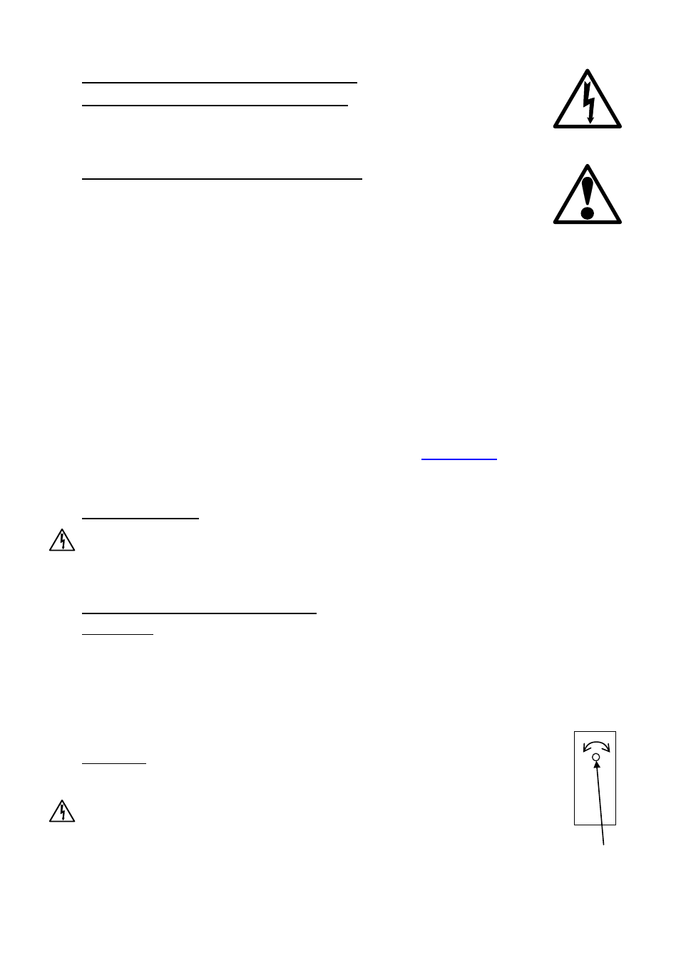
Before connecting the electrical supply, turn the potentiometer on the thyristor fully
to the left (anti-clockwise). This sets the output current of the thyristor to ‘off’.
potentiometer