Installation – Carbolite TZF Series User Manual
Page 3
1700-1800° Tube
MF32 - 3.25
3
2.0 I
NSTALLATION
2.1 Unpacking & Handling
When unpacking or moving the furnace always lift it by its base. Never lift it by its work tube or
the surrounding insulation, or by any protruding parts. These models contain transformers and are
heavy: use of lifting equipment is recommended.
NOTE: This product contains Refractory Ceramic Fibre (better described as Alumino Silicate
Wool) for precautions and advice in handling this material see the ‘Repairs and Replacements’
section.
2.2 Siting & Setting Up
Place the furnace in a well ventilated room, away from other sources of heat, and on a surface
which is resistant to accidental spillage of hot materials. Do not mount the furnace on an
inflammable surface.
Ensure that there is free space around the furnace. Do not obstruct any of the vents in the case:
there are cooling fans in the case which must not be obstructed.
Ensure that the furnace is placed in such a way that it can be quickly switched off or disconnected
from the electrical supply - see below.
2.3 Removal of Packing Material
Remove the cover from the right hand side by slackening the fixing screws through the four access
holes and lifting the cover vertically to release it.
Remove the end insulation retaining plate by unscrewing the four fixing screws and carefully
sliding the plug from the brickbox.
Three pieces of insulation come away with the plate leaving two halves loose inside the furnace.
Remove these to give access to the packing material therein. Carefully remove all packing
material. Note that in the TZF models there are zone barriers comprising insulation pieces which
protrude into the chamber; take care not to damage these pieces.
Model TZF 18/600 – see separate booklet MS12.
Reassemble the insulation by reversing the removal procedure. Now fit the heating elements.
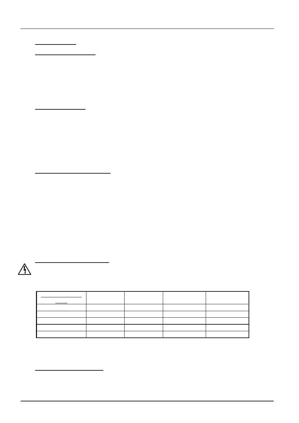
2.4 Fitting the Heating Elements
Wear eye protection when handling the heating elements. See the warning in section 5.6.
The Molybdenum Disilicide elements are
EXCEPTIONALLY FRAGILE
and are packed separately,
together with other items:
Separately packed
items
CTF 17/300
CTF 18/300
CTF 17/600
TZF 17/600
CTF 18/600
TZF 18/600
Elements
6
6
10
10
Element clamps
12
12
20
20
Element clips
12
12
20
20
Braids
1 set
1 set
1 set
1 set
Element insulators
6
6
10
10
Fit the heating elements vertically into the chamber, handling with great care. Installation
instructions are given later in this manual in section 5.6.
Connect the aluminium braids securely as indicated in the element installation instructions.
2.5 Fitting the Thermocouples
The number of thermocouples depends on the model. CTF has two, TZF has four or five
depending on the 3-zone control method. The thermocouples are enclosed in ceramic sheaths