Carbolite CTF Series User Manual
Page 13
MTF, CTF
MF03 3.13
13
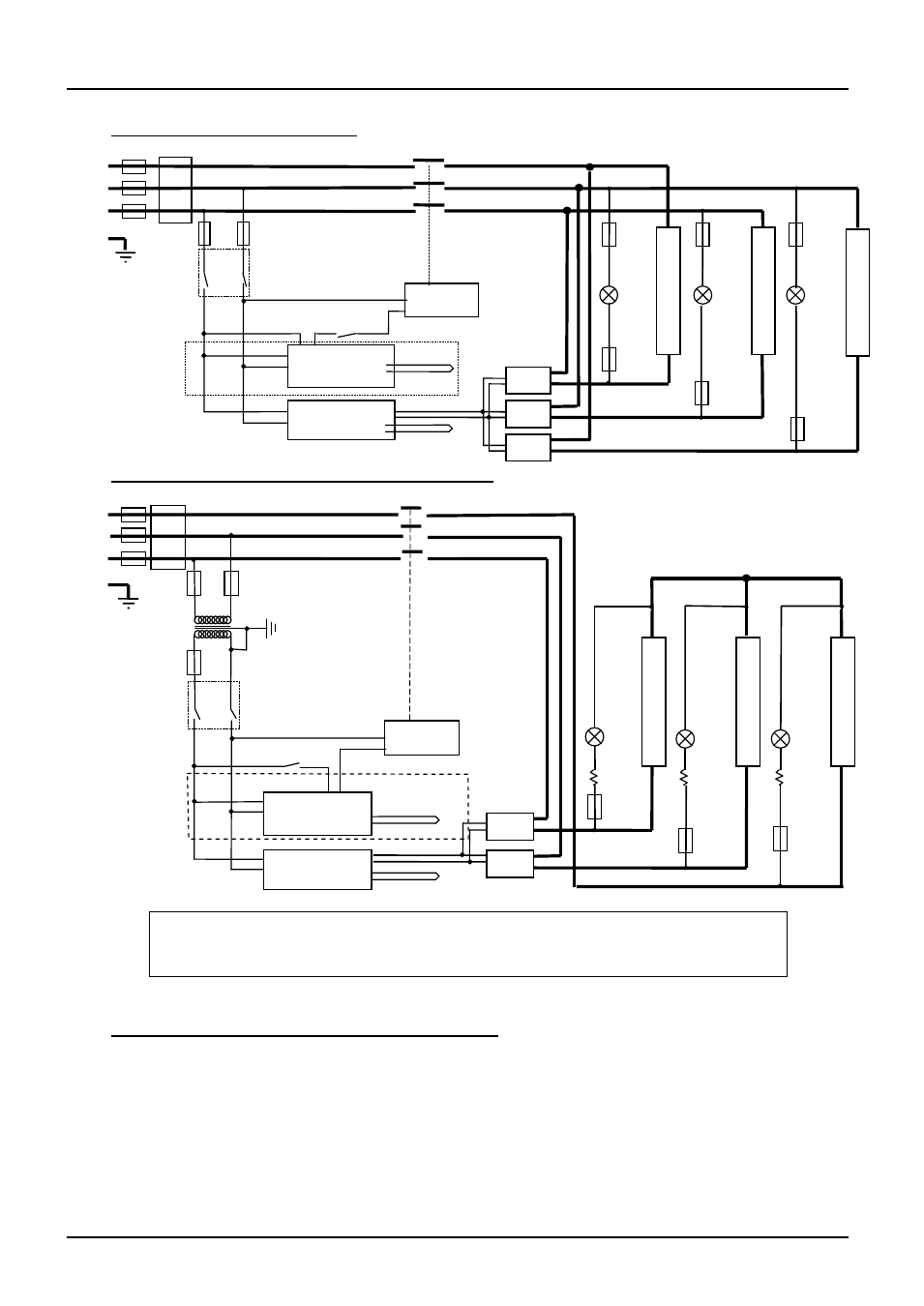
7.4 3-phase without neutral (delta)
7.5 3-phase without neutral (star – e.g. 380 to 415V)
7.6 Higher Voltages (e.g. 254V; 440V, 480V 3-phase)
The diagram above (7.5) normally applies, with neutral (if present) not being used.
For single phase models of 254V or above, diagram 7.1 applies except that a control circuit
transformer is included as in diagram 7.5.
e
l
e
m
e
n
t
(s)
e
l
e
m
e
n
t
(s)
Instrument Switch
coil
temperature
controller
overtemp.
controller
thermocouple
safety
switch
SSR
heat
on
F3
F1
F2
F3
L2
L3
L1
PE
SSR
SSR
F3
heat
on
F3
e
l
e
m
e
n
t
(s)
heat
on
F3
F3
if fitted
thermocouple
contactor
Filter (if fitted)
e
l
e
m
e
n
t
(s)
e
l
e
m
e
n
t
(s)
F1
L2
L3
F2
L1
PE
e
l
e
m
e
n
t
(s)
transformer
coil
temperature
controller
thermocouple
overtemp.
controller
thermocouple
SSR
heat
on
F3
SSR
heat
on
F3
heat
on
F3
Filter (if fitted)
contactor
47k
47k
47k
F2
Note: in this configuration the fuses F2 on the supply side of the transformer may be
GEC Safeclip, not 32 x 6mm glass as stated in section 8.1.
if over-
temperature
fitted
Instrument Switch
Heater Switch