Circuit diagrams – Carbolite CTF Series User Manual
Page 12
MTF, CTF
12
MF03 3.13
7.0 C
IRCUIT
D
IAGRAMS
Safety Switches type A: a 2-pole Heater Switch is fitted directly in the element circuit in models
up to 16A rating.
Safety Switch type B: a Heater Switch is fitted into the contactor coil circuit in models over 16A.
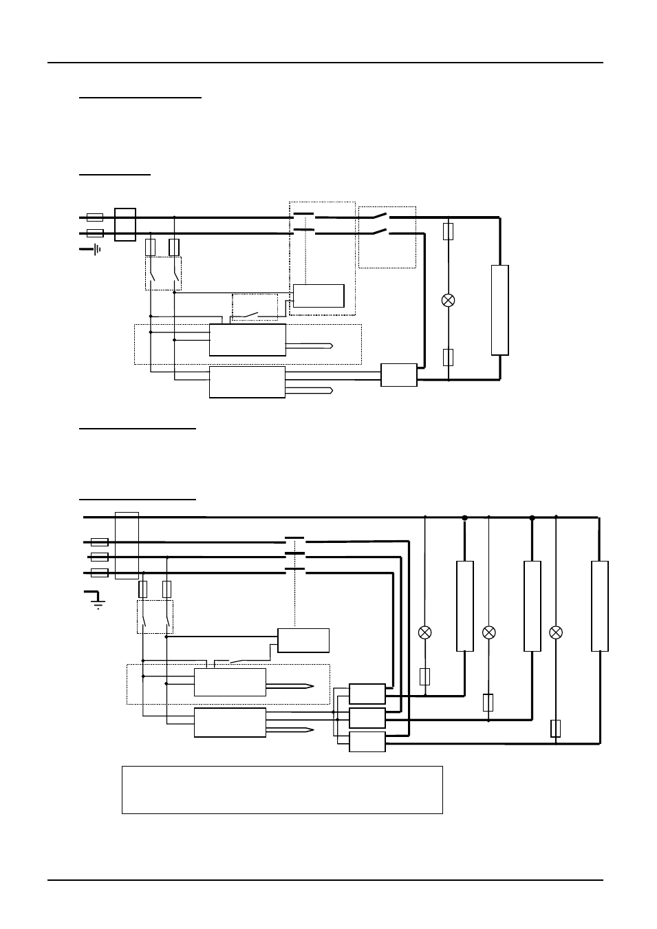
7.1 Single Phase
7.2 2-phase with neutral
As 3-phase, with phase L3 not present, and with two SSRs and element circuits. In models up to
25A safety switches type A are fitted in the L1 and L2 circuits instead of type B in the contactor
coil circuit.
7.3 3-phase with neutral
note on 3-phase: depending on filter(s) fitted, there may be 3
separate neutral wires from the elements to the neutral supply.
e
l
e
m
e
n
t
(s)
e
l
e
m
e
n
t
(s)
F1
N
L2
L3
F2
L1
PE
e
l
e
m
e
n
t
(s)
Instrument Switch
coil
temperature
controller
overtemp.
controller
safety
switch
SSR
heat
on
F3
SSR
SSR
heat
on
F3
heat
on
F3
Filter (if fitted)
if fitted
thermocouple
thermocouple
contactor
Instrument Switch
coil
temperature
controller
thermocouple
overtemp.
controller
thermocouple
safety
switch B
SSR
e
l
e
m
e
n
t
(s)
heat
on
safety
switches A
F3
F1
F2
F3
N
L
PE
Filter
(if fitted)
contactor
if fitted
if fitted