Fuses & power settings – Carbolite HRF (MF05) User Manual
Page 13
HRF
MF05 – 3.25
13
8.0 F
USES
&
P
OWER
S
ETTINGS
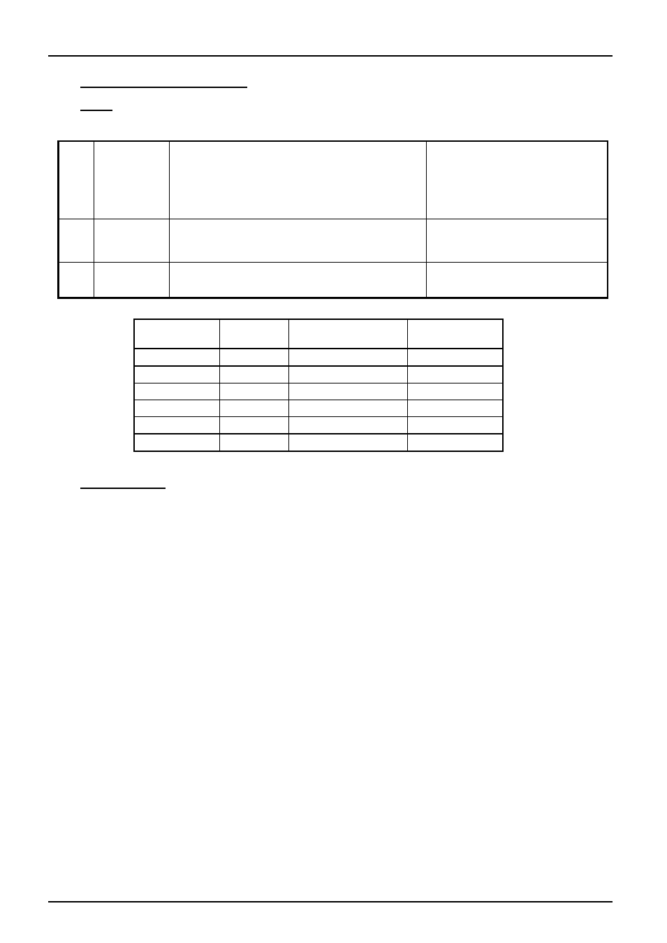
8.1 Fuses
F1-F3: Refer to the circuit diagrams.
F1
Internal
supply
fuses
Fitted if supply cable fitted.
Fitted on board to some types of EMC filter.
on-board and up to 16 Amps:
32mm x 6mm type F
later models: 38mm x 10mm
other: GEC Safeclip or Ferraz
to suit supply rating
F2
Auxiliary
circuit
fuses
Fitted on board to some types of EMC filter.
2 Amps glass type F
On board: 20mm x 5mm
Other: 32mm x 6mm
Customer
fuses
Required if no supply cable fitted.
Recommended if cable fitted.
See rating label for amperage;
see table below for fuse rating.
Model
phases
Volts
Supply Fuse
Rating
HRF 7/22
1-phase
220-240
15A or 16A
HRF 7/22
1-phase
200-208
15A or 16A
HRF 7/112
3-ph+N
380/220 – 415/240
30A or 32A/ph
HRF 7/112
3-ph delta
220-240
50A/ph
HRF 7/324
3-ph+N
380/220 – 415/240
40A/ph
HRF 7/324
3-ph delta
220-240
60 or 63A/ph
8.2 Power Settings
For models made for 254 volts or 440 volts the power limit parameter
OP.Hi
may be set to 89%. If
in doubt please contact Carbolite.
For all other models in this manual the power limit parameter
OP.Hi
is set to 100%.
HRF 7/22: Note that the 208V model can safely be used on a 240 supply if and only if the power
limit is changed to 75%.
Fan
Motor
Capacitor
BU R R1