Circuit diagrams – Carbolite HRF (MF05) User Manual
Page 12
HRF
12
MF05 – 3.25
7.0 C
IRCUIT
D
IAGRAMS
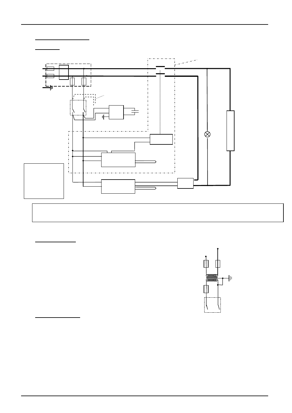
7.1 HRF 7/22
7.2 Higher Voltages
For 254V (or above) an isolating transformer is fitted in the
control circuit after the F2 fuses.
7.3 Industrial Models
Circuit diagrams are supplied separately for these models.
KEY
BU = light blue
BR = brown
R = red
Instrument Switch
coil
temperature
controller
thermocouple
overtemp.
controller
thermocouple
SSR
e
l
e
m
e
n
t
(s)
heat
on
F1
F2
N
L
E
EMC Filter
contactor
R
BU
Fan
Motor
Capacitor
BR
BU
if overtemperature fitted
see note
note: In HRF 7/22 before late 2003 the fan was connected to the live side of the Instrument switch.
In later models the fan is connected to the switched side of the Instrument switch.
F2
F2
transformer
Instrument Switch