AMMCO 4850 Brake Drum Grinder User Manual
Page 3
AMMCO Brake Drum Grinder • 3
GRINDING THE DRUM
Brake drums may be finished in either of two ways:
Two Step Process - Each brake drum is mounted on
the brake lathe arbor, rough turned and then finish
ground before moving on to the next drum. Only the
boring bar and the grinder are interchanged to main-
tain the absolute accuracy that is necessary for the
professional brake job. DO NOT turn all the drums
then remount and grind each one.
One Step Process - Brake drums with little wear or
those with no out-of-round distortions may simply be
finish ground without prior machining. DO NOT
exceed the recommended depth-of-grind .002" to
.005" (.051 to .127 mm) on any one pass.
The position of the clamp must not be changed
until the set of drums for which the grinding wheel
was dressed have been ground.
Remove the dresser from the drum wall. Check to be
sure that the lathe motor switch is OFF. Adjust the
lathe spindle manually to bring the drum back over the
grinding wheel as far as possible. It may be necessary
to turn the wheel guard on the grinder spindle to gain
clearance. Loosen the wheel guard cap screw to do
this, but DO NOT remove the wheel guard. Also it is
wise to turn the drum by hand for at least one revolu-
tion to make sure that everything is clear.
CAUTION: Always wear safety glasses while
operating grinder.
1. Set the lathe spindle speed to its slowest R.P.M.
2. Start the grinder and the lathe.
3. Use the cross feed handwheel to move the grind-
ing wheel into contact with the drum wall.
4. Set the depth-of-grind from .002" to .005" (.051 to
.0127 mm).
5. Set the infimatic spindle feed from .008" to .010"
(.203 to .254 mm). Engage the feed mechanism.
6. Set the feed stop so that the spindle will automat-
ically stop feeding when the grinding wheel clears the
drum.
Turn, then grind each of the remaining drums of the
set in the same manner. Remember—it is not neces-
sary to dress the grinding wheel for each drum—only
when the grinding angle is changed, when the wheel
becomes “loaded” or dull, or when a new wheel is
installed.
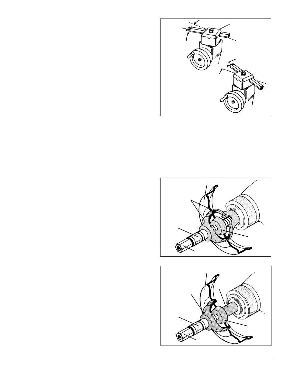
NOTE: Figure 5 illustrates the positioning of the
boring bar clamp for large and small drums. Once
setup for one or the other, the tool post pivot set
screw is locked.The boring bar clamp is not moved
when the boring bar is exchanged with the
grinder.
Figure 5
Hubless drum 10" (254 mm) and smaller may also be
turned and finish ground on AMMCO lathes. These
smaller drums must be mounted differently than full
size types. The larger diameter hubless adapter
(shown in Fig. 6a) on the inside of the drum is NOT
used. Instead, an appropriately sized centering cone
and a spacer are used on the inside with the hubless
adapter on the outside. This clears a working area for
both cutting and grinding, Fig. 6b.
Figure 6a - Mounting For Hubless Drums Over 10" (254mm)
Figure 6b - Mounting For Hubless Drums 10" (254mm) And
Under
Boring Bar Clamp
Swiveled For
Large Diameter
Brake Drums
Swiveled For
Small Diameter
Brake Drums
Centering
Cone
Arbor Nut
Spacer
Cross Section Of Hubless Brake Drum
Self-Aligning
Spacer
Hubless Adapter
Cones
Centering
Cone
Arbor Nut
Cross Section Of Hubless Brake Drum
Self-Aligning
Spacer
Hubless
Adapter
Cone