AMMCO 4850 Brake Drum Grinder User Manual
Page 2
2 •
AMMCO Brake Drum Grinder
GRINDER INSTALLATION
After the first brake drum has been turned, remove
the boring bar from the clamp and place the grinder in
position, Fig. 1. DO NOT overtighten the clamp on
the grinder spindle housing. For proper setup, be
sure to move the lathe spindle manually to its full back
position. DO NOT plug in the grinder power cord
until the grinder is completely setup.
Figure 1 - Grinder Installation
MOUNTING THE GRINDING WHEEL
To mount the grinding wheel, insert the Grinding
Wheel Removal Tool, (Item 28) on the parts drawing,
through the spindle housing to lock the spindle. Install
the new wheel, Fig. 2.
Figure 2 - Mounting The Grinding Wheel
Before proceeding further, the grinding wheel must
be dressed. Dressing cleans, shapes, and trues the
surface of the grinding wheel. Refer to the instruction
sheet for the No. 906061 Grinding Wheel Dresser
(PN/921109).
SAFETY PRECAUTIONS: When dressing a grind-
ing wheel, extra care must be taken to protect the
operator. The lathe must not be turned on while
dressing the grinding wheel with a drum-mounted
dresser. Be sure the dresser is removed from the
drum before starting the lathe.
GRINDING WHEEL DRESSING
The No. 906061 Diamond Wheel Dresser is used to
true the surface of the grinding wheel to be parallel
with the surface of the machined drum. The diamond
nib cleans and shapes the wheel to assure full grind-
ing wheel contact.
The grinding wheel is normally dressed one time to
finish grind one set of brake drums. However, if the
grinding wheel gets dull or “loaded”, redress it.
Dressing takes but a moment-don’t overlook it. Note
that the Grinding Wheel should be dressed before fin-
ishing each drum.
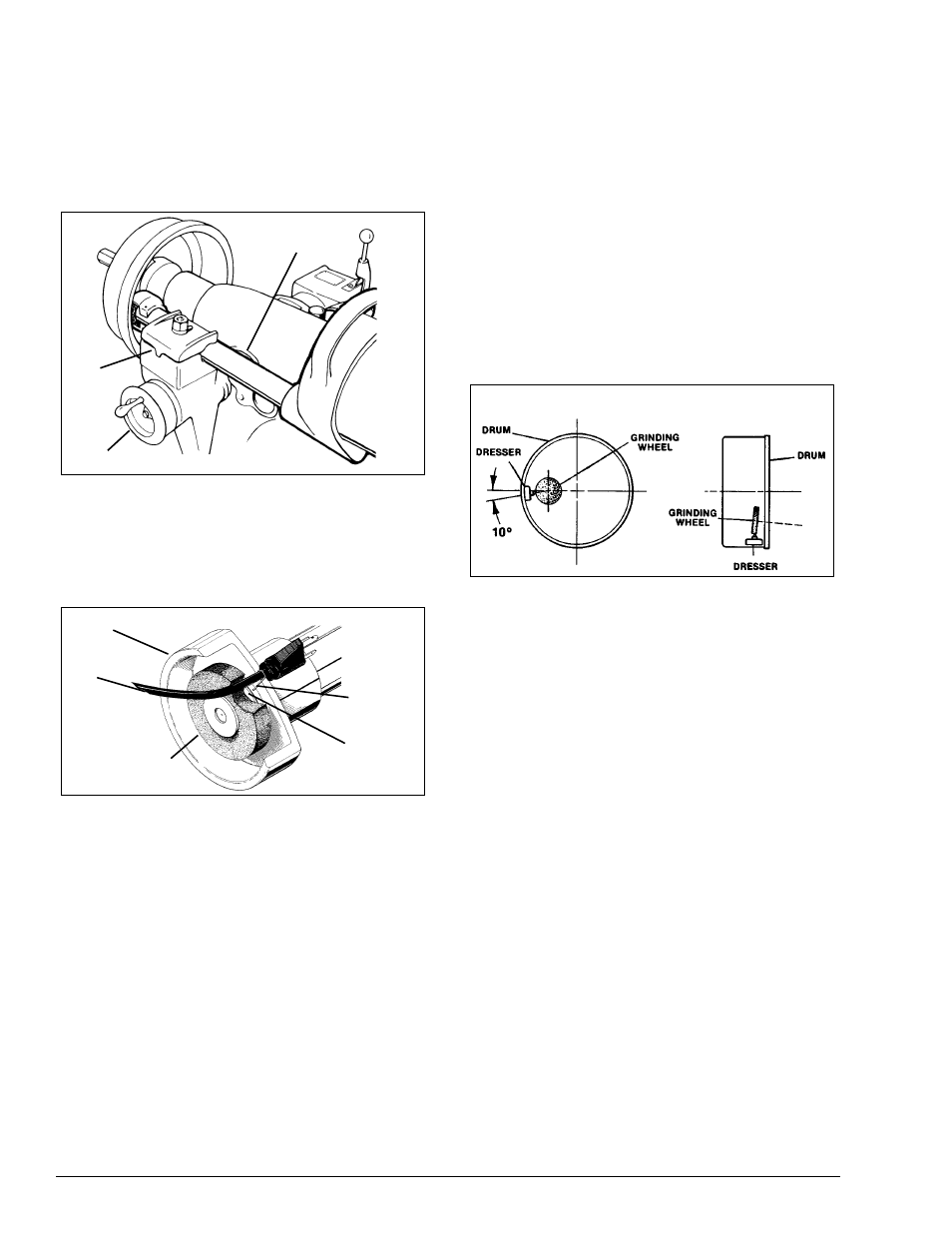
1. The dresser is magnetically held inside the drum
on the same surface that will be ground. Visually align
the diamond tip 10-degrees below the center of the
Grinding Wheel, as shown in Fig. 3. This is particularly
important when dressing the Grinding Wheel at an
angle, Figure 4.
The Drum Grinder should be securely mounted in the
Boring Bar Clamp of the Lathe.
It may be necessary to remove the silencer band
when mounting the dresser.
Figure 3 & 4 - Visually Align Diamond Tip
2. Make sure that the grinding wheel will clear the
brake drum after it passes the diamond nib. Manually
move the lathe spindle back and forth to check this.
Use the cross feed hand wheel to adjust clearances.
CAUTION: The grinding wheel spins at a high
speed. DO NOT use a damaged wheel. DO NOT
use the grinder with the wheel guard removed.
WEAR SAFETY GOGGLES AT ALL TIMES!
3. Plug in the grinder power cord and turn the switch ON.
Use the cross feed hand wheel to move the grinding
wheel until it just touches the diamond. Using the
spindle feed hand wheel, manually move the diamond
tip back and forth across the grinding wheel face. Set
the depth-of-cut at about .005" (.127 mm) per pass.
Dress the grinding wheel until its full face is par-
allel to the drum wall. DO NOT overdress or use
too fast a spindle feed. Moving the dresser across
the wheel too fast will leave too rough a surface on
the face of the wheel.
4. After dressing a wheel, do not change the position
of the Boring Bar Clamp in which the Grinder is
mounted. Remove the Dresser from the drum wall
and, after loosening the knurled set screw, rotate the
diamond nib slightly. This will help keep the nib
pointed and prolong its life — as well as set it up for
the next dressing job.
Spindle Housing
Boring
Bar
Clamp
Cross Feed Handwheel
Grinding Wheel Guard
Power Cord
Grinding Wheel
Removal
Tool
Hole
Figure 4
Figure 3